Injection molding machine for bimaterial molding and method of controlling the same

A technology of an injection molding machine and a control method, which is applied in the field of injection molding machine for dual-material molding and its control, can solve the problems of difficult mold replacement, difficult rotation of the central axis, difficult high-precision rotation of the mold, etc., so as to prevent mold damage and avoid collision effect

Active Publication Date: 2010-11-17
MITSUBISHI HEAVY INDS PLASTIC TECH
View PDF9 Cites 27 Cited by
  • Summary
  • Abstract
  • Description
  • Claims
  • Application Information

AI Technical Summary

Problems solved by technology

In addition, the rotating die is supported on a member protruding from the fixed plate so that it can rotate freely and move freely toward the movable die side. However, since it is a cantilever member, it does not have a sufficiently rigid structure. Accurately supports heavy rotating molds
Since the rotating disk is added between the strokes of the fixed disk and the movable disk of the conventional molding machine, it is difficult to obtain a sufficient movement stroke of the movable disk and the rotating disk for the rotary operation of the rotary mold with a large lateral width.
In addition, the parts extending from the fixed plate that support the rotating mold are divided into upper and lower parts, and must be installed on the fixed plate separately up and down. It is difficult to make the upper and lower rotation centers concentric, and problems such as adhesion and wear of the bearing part may occur when the rotating mold rotates.
In addition, in order to reduce the weight of the rotating mold, the two side molds and the mold rotating shaft are integrated, so it is difficult to replace the mold

Method used


Image

  • Injection molding machine for bimaterial molding and method of controlling the same
  • Injection molding machine for bimaterial molding and method of controlling the same
  • Injection molding machine for bimaterial molding and method of controlling the same

Examples


no. 1 approach

[0075] The injection molding machine for two-material molding of this embodiment has two cavities formed by a mold for a movable platen, a mold for a fixed platen, and a mold for both sides of a rotating platen disposed between the two platens. Different types of resins are injected separately, and the rotary platen is rotated 180 degrees to perform double injection, and the two materials are integrally molded. Among them, it is easy to drive the movement of the movable platen and the rotary platen, and the rotation of the rotary platen. Electric drive unit for control.

[0076] Next, a first embodiment will be described with reference to the drawings.

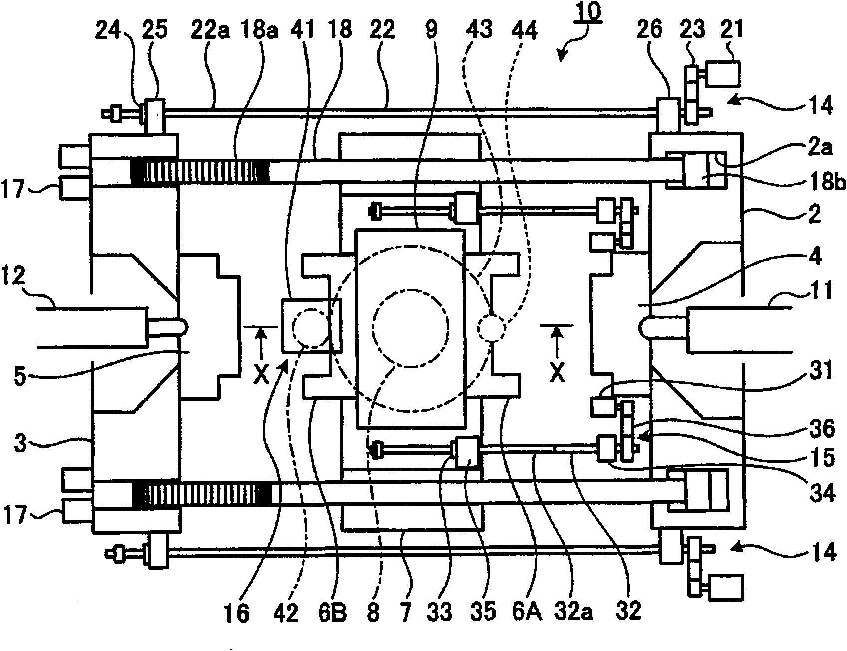
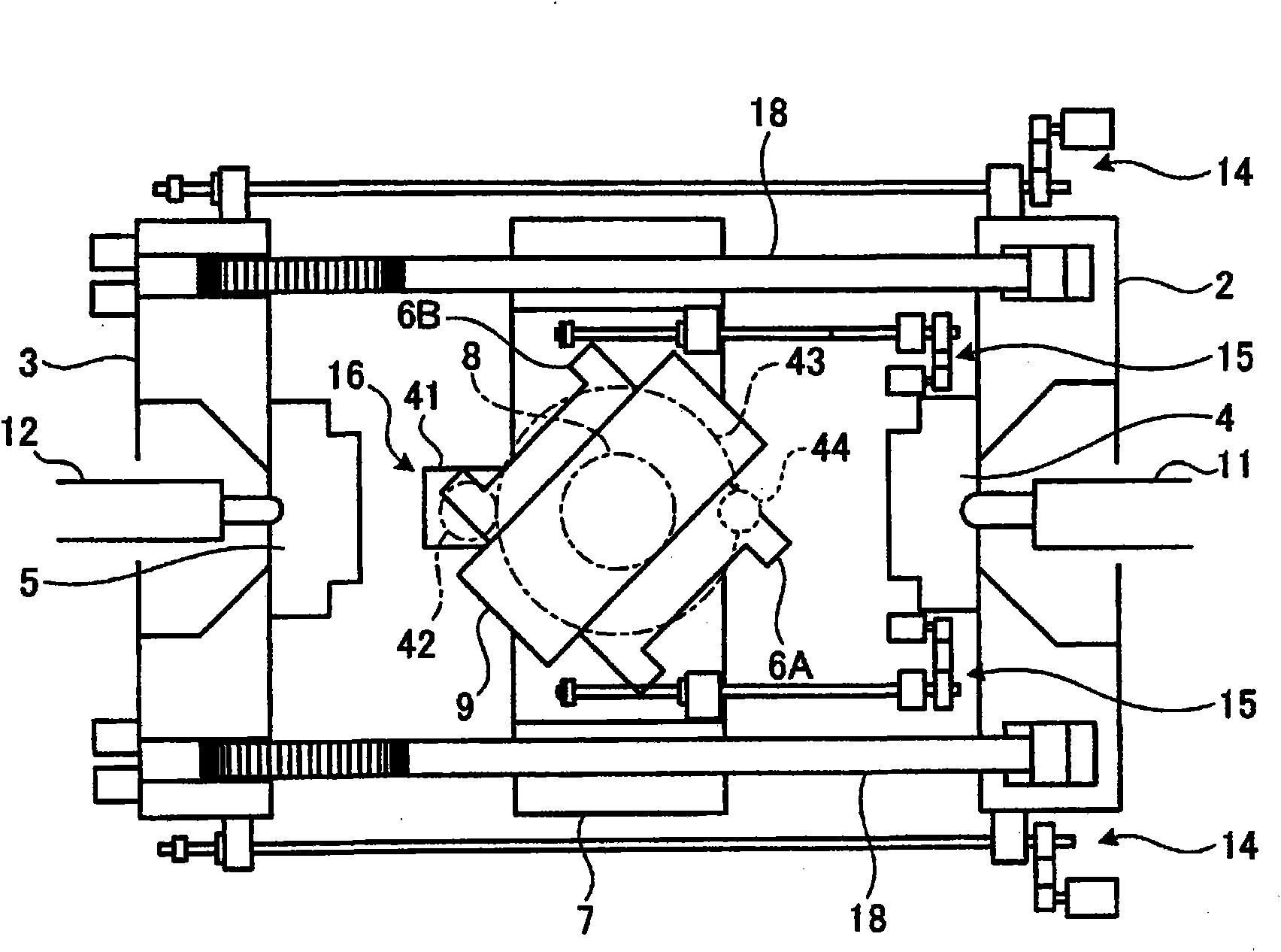
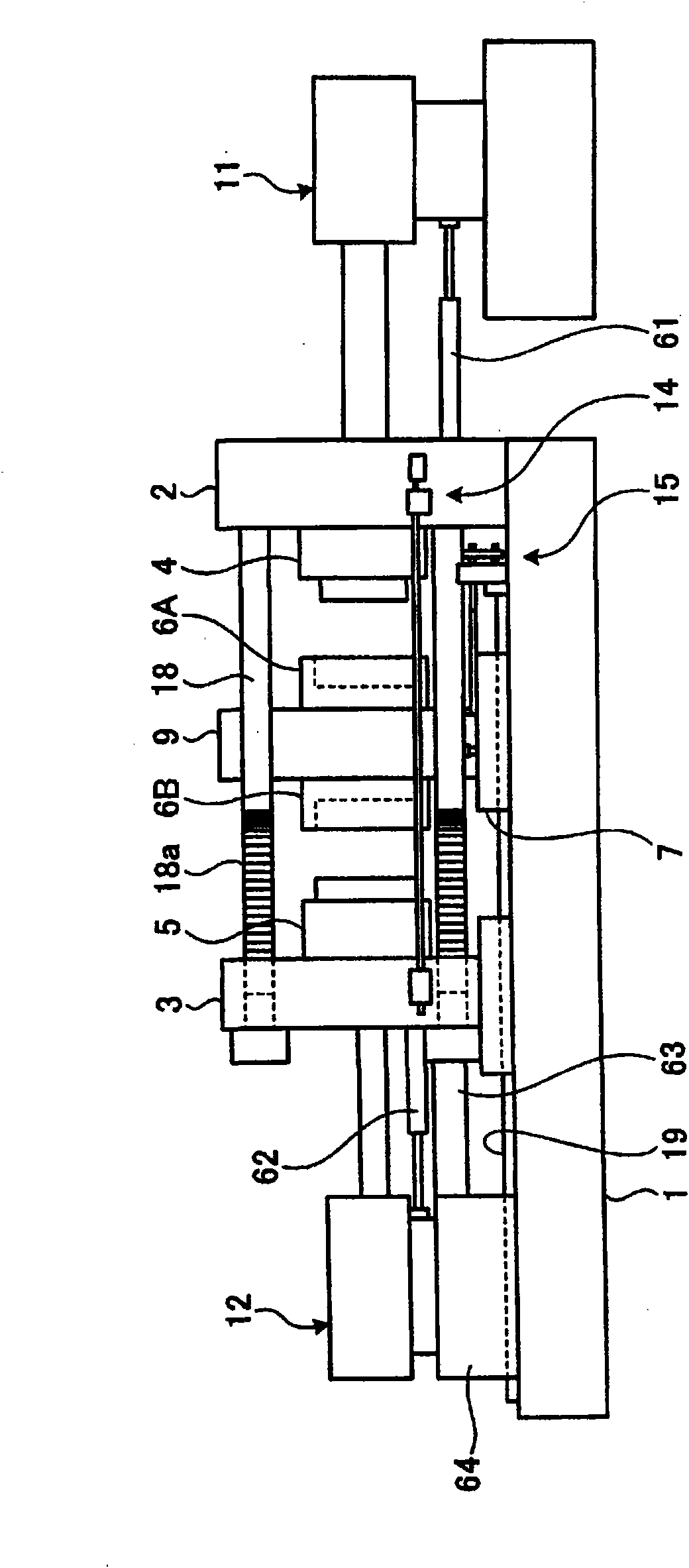
[0077] figure 1 It is a schematic plan view of the injection molding machine for two-material molding of the present invention. figure 2 yes means figure 1 A diagram of the rotation action of the rotary platen of the injection molding machine for bi-material molding. image 3 yes figure 1 Side view of an injection moldin...

no. 2 approach

[0131] Next, a second embodiment of the present invention will be described. This second embodiment differs from the first embodiment in that, as Figure 7 As shown in the schematic plan view of the injection molding machine 30 for bi-material molding, the servo motor A (21) and the ball wire are provided on the reversing table 7 to drive the movable die plate opening and closing unit 46 of the movable die plate 3. The support base 26 of the lever shaft 47 is the same as that of the first embodiment except for that, and therefore description of other structures will be omitted.

[0132] The advantage of the second embodiment is that the ball screw shaft 47 can be shortened, so the critical speed of the ball screw shaft 4 is increased, and the opening and closing speed of the movable platen 3 can be increased. In addition, since the ball screw is directly used to connect the rotating mounting plate 9 and the movable mounting plate 3, it is not necessary to detect and control t...

no. 3 approach

[0134] Next, a third embodiment of the present invention will be described. This second embodiment differs from the first embodiment in that, as Figure 8 As shown in the schematic side view of the rotary mounting plate, the rotary mounting plate rotating unit 50 is composed of a servo motor C (41) mounted on the reversing table 7, a pinion 53 mounted on the servo motor C (41), and a pinion 53 The meshing rotary mounting plate 9 is composed of a large gear 52 integrally provided, and an endless toothed belt 54 wound around the pinion 53 and the large gear 52, and is a rotational drive that rotates the rotary mounting plate 9 in the forward and reverse directions for half a turn. The unit is the same as that of the first embodiment except for that, so descriptions of other structures are omitted.

[0135] According to this embodiment, its advantage is that it is not necessary to directly contact the large gear 52 and the pinion 53, and the distance between the rotation axis of...


PUM


Abstract

An injection molding machine for bimaterial molding equipped with two sets of injection units (11,12) capable of plasticization and injection filling of different resin materials, respectively, which injection molding machine comprises, as mold clamping means, hydraulic mold clamping means for simultaneously clamping three sets of die plates (2,3,9); as movable die plate opening/closing means (14), movable die plate opening/closing means driven by an electric motor; as rotary die plate opening/closing means (15), rotary die plate opening/closing means (14) driven by an electric motor; and, asrotating means for a rotary die plate (9), rotational driving means driven by an electric motor mounted on a reversal pedestal (7).

Description

technical field [0001] The present invention relates to the following injection molding machine for two-material molding: from two sets of injection units to the mold of the movable platen, the mold of the fixed platen and the two sides of the rotary platen arranged between the two sets of platens The two cavities formed by the mold are injected with different types of resin, so that the rotating platen is rotated 180 degrees for two-layer injection, and the two materials are integrally formed, especially when it is easy to control the moving speed of the movable platen and the rotating platen An injection molding machine for two-material molding with a moving unit and a rotating unit that can easily control the rotating speed of the rotary loading plate, and a method for controlling the moving speed and rotating speed. Background technique [0002] An example of a molding method for obtaining molded products of different materials and colors by an injection molding machine ...

Claims


Application Information

Patent Timeline
Patent Type & Authority Applications(China)
IPC IPC(8): B29C45/12B29C45/16B29C45/68B29C45/76
CPCB29C2945/76605B29C2945/76936B29C45/68B29C2945/76866B29C2945/76598B29C2045/1792B29C45/045B29C45/1628B29C2945/76337B29C45/80B29C2945/76314
Inventor 加藤直纪松下博乙大河内康夫大关泰明佐治政光苅谷俊彦
Owner MITSUBISHI HEAVY INDS PLASTIC TECH
Why Eureka
Try Eureka