Rotary drive device of a polishing device

Inactive Publication Date: 2005-06-28
TEIJIN SEIKI CO LTD
View PDF4 Cites 2 Cited by
  • Summary
  • Abstract
  • Description
  • Claims
  • Application Information

AI Technical Summary

Benefits of technology

[0017]More specifically, the internally contacting cylinder has a plurality of recesses, and is integrally engaged with the outside ring (output shaft) of the double hollow rings sandwiching rollers mounted in the recesses therebetween. According to this construction, the shape of the floating ring (hollow ring-shaped internally contacting cylinder) which has been in a truth circle is deformed in a wavy shape in the elastic region whereby pressing force is generated. Thus, the rotation of the polishing table, the table for CMP or the polisher can achieve high rotation precision (change of a rotational speed, vibration, fluctuation of the table surface being small), and the wafers can be processed in a highly precision.
[0018]Furthermore, as illustrated in the embodiment, according to the present invention, it is preferred that the internally contacting cylinder is coupled with the polishing table, the table for CMP or the polisher by means of a pin or a key.

Problems solved by technology

However, in that case of conventional DD motor system, there was a problem that it is voluminous and heavy.
Because of this, the problem intensifies more.
On the other hand, in order to obtain an evenness of high dignity in a wafer, it is an important problem for CMP that changes and vibration in a rotational speed of a

Method used


Image

  • Rotary drive device of a polishing device
  • Rotary drive device of a polishing device
  • Rotary drive device of a polishing device

Examples


Embodiment Construction

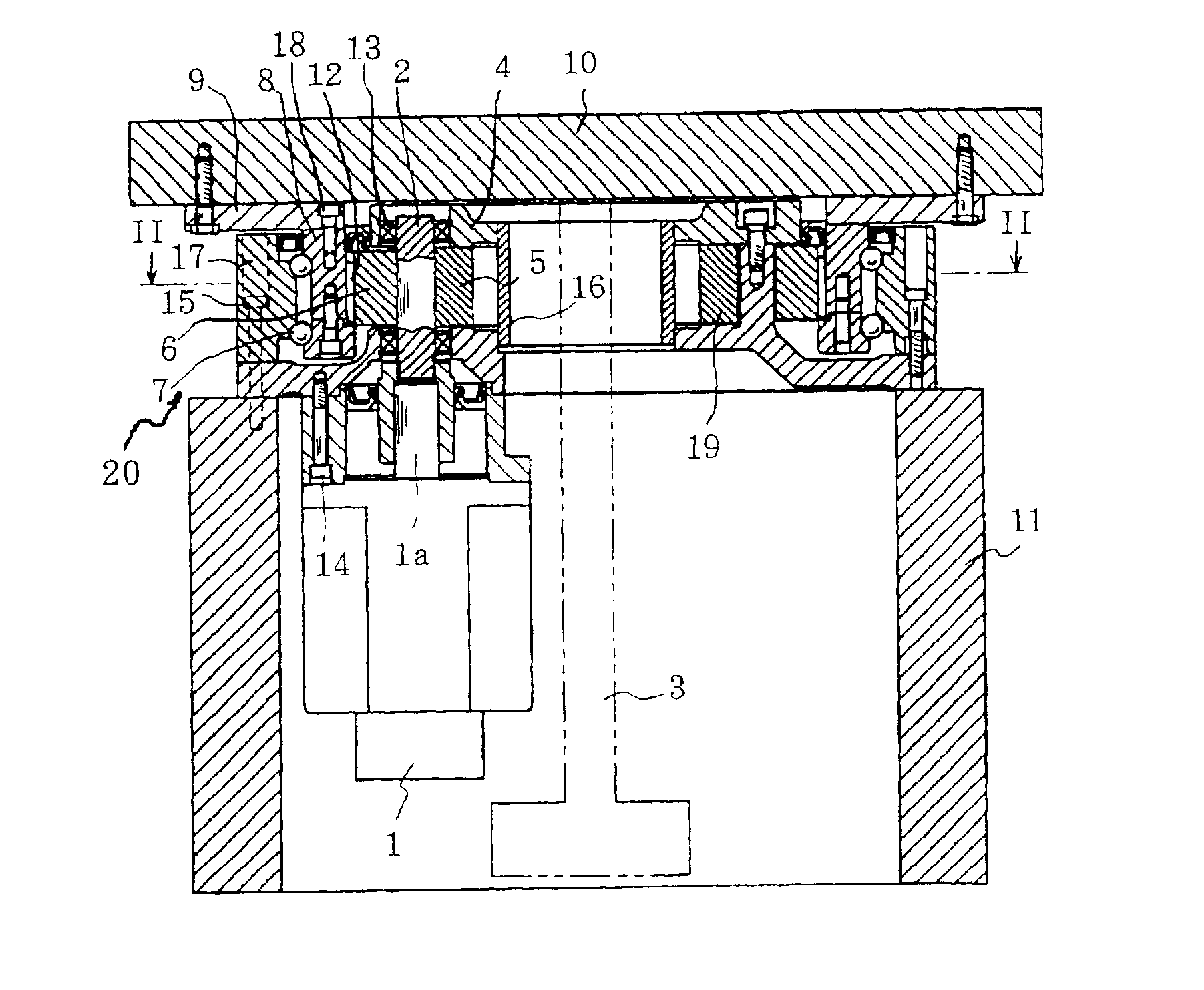
[0031]In a preferred embodiment illustrated in FIG. 1, reference numeral 10 denotes a table, on which semiconductor wafers or liquid crystal glass are mounted and which is pushed by polisher (not shown) from the top, and it is used to flatten an end face of the wafers or an end face of liquid crystal glass. The table 10 is disposed on a frame 11 and, as will be described later, it can be rotated in a horizontal plane by a drive motor through a traction drive type reduction gear 20.

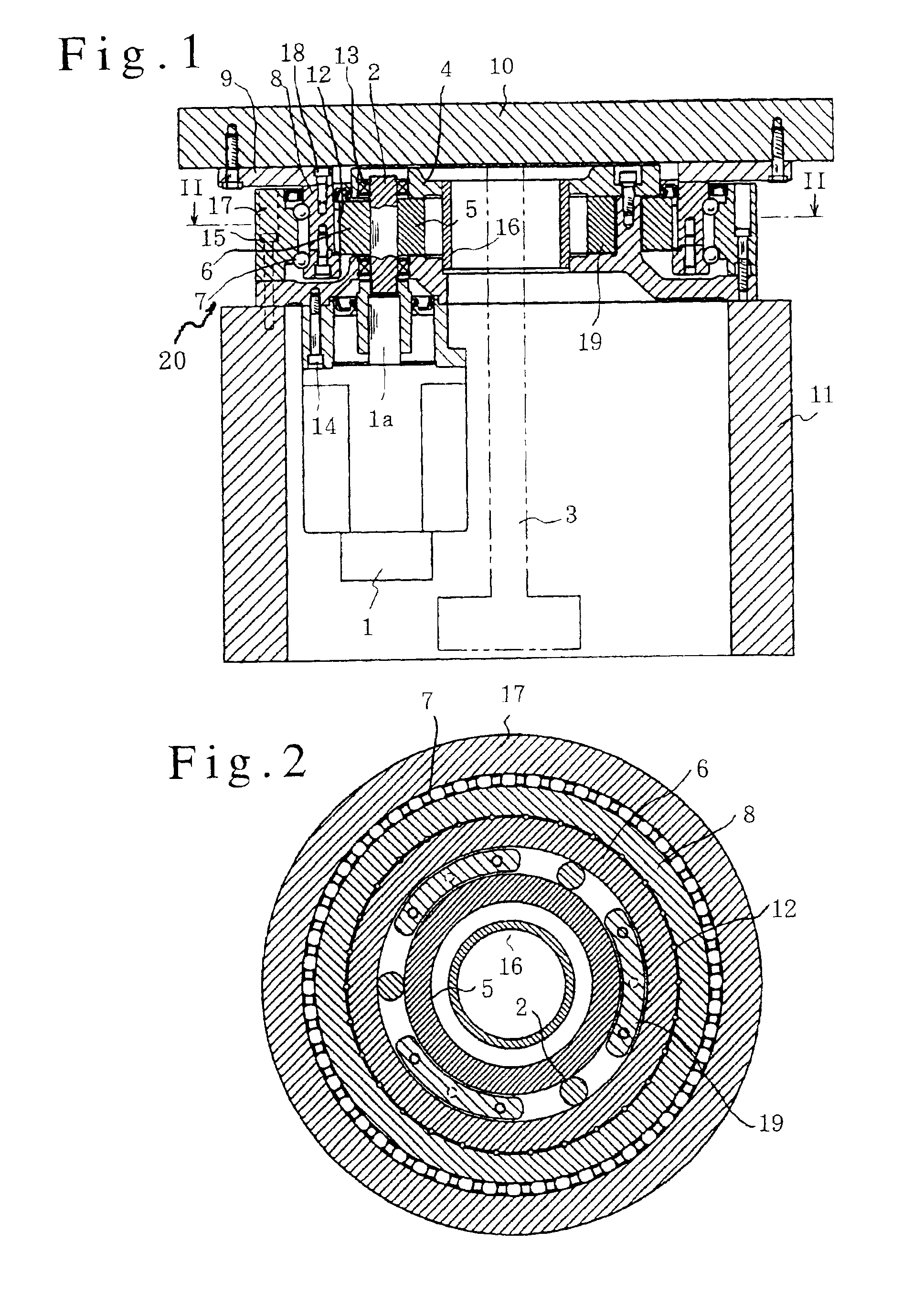
[0032]Referring to FIG. 2, an embodiment of a rotary drive device according to the present invention will be explained. An externally contacting shaft 5 formed in a ring-shaped hollow cylinder is disposed at the rotational center of the table 10 by means of a carrier 4 (FIG. 1). A plurality of (3 in FIG. 2) intermediate shafts 2 are equidistantly disposed at the circumference of the externally contacting shaft 5, and as illustrated in FIG. 1, they are supported rotatably on the carrier 4 by means of bearin...


PUM


Abstract

A polishing device having a table connected to a traction drive type reduction gear. The reduction gear includes an externally contacting shaft formed in a ring-shaped hollow cylinder and arranged at the center; a plurality of intermediate shafts which are equidistantly disposed at the circumference of the externally contacting shaft, at least one of which is an input shaft; and an internally contacting cylinder with which the intermediate shafts internally contact, and under free conditions, the externally contacting shaft formed in a hollow cylinder has a diameter which is a little bit larger than a diameter of an imaginary circle which externally contacts with a plurality of intermediate shafts whereby pressing load is created by means of deformation of the hollow cylinder.

Description

BACKGROUND OF THE INVENTION[0001]1. Field of the Invention[0002]The present invention relates to a rotary drive device of a polishing device. More specifically, the present invention relates to a rotary drive device of a polishing table, a table for CMP (Chemical Mechanical Polishing) or polisher which is used to flatten an end face of a semiconductor wafer or an end face of liquid crystal glass.[0003]2. Description of Related Art[0004]Conventionally, a method called CMP (Chemical Mechanical Polishing) is used to flatten semiconductor wafers and so on. In short, a wafer is put on a turn table, then, the wafer is pushed to the turn table by a polisher and is polished thereby having slurry sprayed between the wafer and turn table (for example, see Japanese Patent Laid-Open No. Hei 8-167585).[0005]It is necessary to drive this turn table and / or the polisher at low vibration and with low noise, and accordingly a direct drive motor of a low rotating speed, which will be referred to as DD...

Claims


Application Information

Patent Timeline
IPC IPC(8): B24B47/00B24B47/12B24B41/00B24B37/04B24B41/04B24B41/047F16H13/02F16H13/08H01L21/304
CPCB24B37/04B24B47/12B24B41/04
Inventor WANG, HONG YOUKAWASHIMA, KOJI
Owner TEIJIN SEIKI CO LTD
Why Eureka
Try Eureka