Fixing apparatus and image forming apparatus provided therewith

a technology of fixing rollers and fixing rollers, which is applied in the direction of electrographic process apparatus, instruments, optics, etc., can solve the problems of long warm up time, inability to keep up with the surface temperature of the fixing roller, and poor heat transfer efficiency, and achieves quick release/contact operation in a small space and low power without encouraging deterioration of the belt member.

Inactive Publication Date: 2007-09-20
SHARP KK
View PDF5 Cites 29 Cited by
  • Summary
  • Abstract
  • Description
  • Claims
  • Application Information

AI Technical Summary

Benefits of technology

[0018]An object of the present invention is to provide a fixing apparatus including an external release / contact mechanism that can realize a quick release / contact operation in a small space and at low power without encouraging deterioration of a belt member. The invention also provides an image forming apparatus provided with such a fixing apparatus.

Problems solved by technology

However, due to poor heat conductivity of the elastic layer, the efficiency of heat transfer suffers greatly when the heat source is provided inside the fixing roller having the elastic layer.
As a result, a long warm up time is required, and, when the transport speed of sheets is increased, the surface temperature of the fixing roller cannot keep up with it.
A problem of this method, however, is that when the fixing roller is stopped at the end of fixing, the fixing roller is locally heated in a portion where the heating member for heating the belt member is in contact with via the belt member.
This causes localized overheating in the fixing roller, in a portion in contact with the belt-suspending rollers via the belt member.
The problem of overshoot due to temperature gradient is particularly prominent when the belt-suspending rollers and the endless belt have small heat capacities as it is usually the case.
Further, overshoot disturbs temperature distributions on the surface of the fixing roller.
This may cause uneven glossiness in images produced in the next fixing process.
However, as described above, since the pre-set temperature of the belt-suspending rollers is higher than the fixing temperature, it takes time to lower the temperature of the fixing roller.
Further, with the external heating section separated from the fixing roller, the heat of the belt-suspending roller does not easily transfer to the fixing roller.
However, there is a problem in the arrangement in which the external heating section is separated from the fixing roller.
Specifically, the belt member deteriorates at an increased rate if the belt member is completely separated from the fixing roller.
This deteriorates the belt member.
Further, in the arrangement in which the belt member is completely separated from the fixing roller, the belt member needs to travel a long distance and therefore requires a large space for the release / contact.
This poses space restrictions.
Further, since the distance of travel is long, the release / contact mechanism requires a large and complex structure, which makes it difficult to realize the quick release / contact as attained by a simple release / contact mechanism.
However, this publication does not describe a specific structure for the release / contact mechanism, nor does it mention which member of the external heating section is separated or made contact.
As such, the technique described in Patent Publication 1 cannot be used to solve the problem of accelerated deterioration in the belt member or realize quick release / contact in a small space and at low power.

Method used


Image

  • Fixing apparatus and image forming apparatus provided therewith
  • Fixing apparatus and image forming apparatus provided therewith
  • Fixing apparatus and image forming apparatus provided therewith

Examples


first embodiment

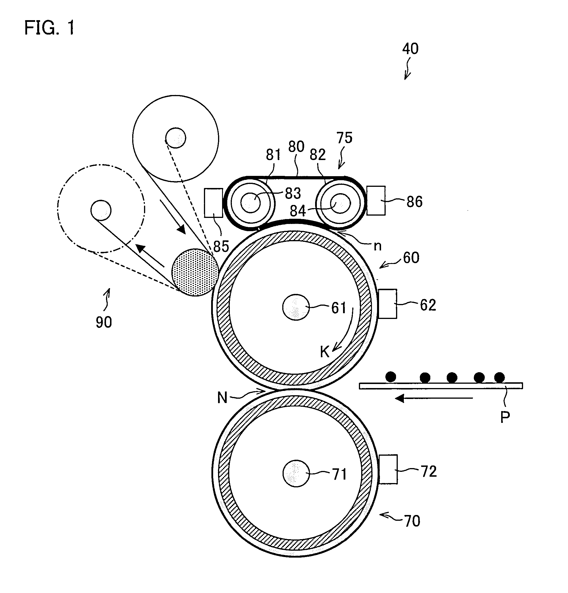
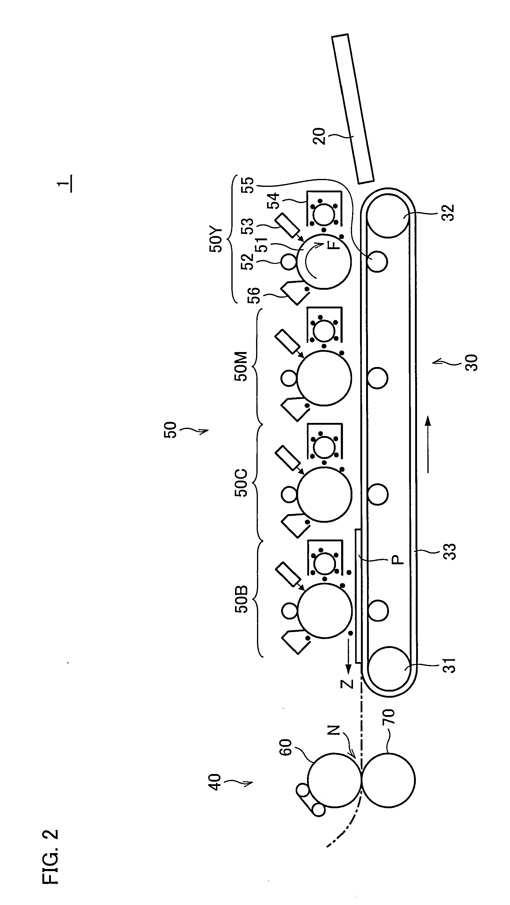
[0041]The following will describe one embodiment of the present invention with reference to FIG. 1 through FIG. 5. First, referring to FIG. 2, description is made as to an image forming apparatus provided with a fixing apparatus according to one embodiment of the present invention. FIG. 2 is a diagram illustrating an internal structure of the image forming apparatus.

[0042]An image forming apparatus 1 shown in FIG. 2 forms a color image or a monochromatic image on paper (printing medium) P based on image data. In this embodiment, description will be made based on a four-tandem-engine color printer of a dry electrophotographic system. The image data is transmitted via a network or read out by a scanner.

[0043]The image forming apparatus 1 includes a visualized image forming section 50, a sheet transport section 30, a fixing apparatus 40, and a paper feed tray 20.

[0044]The visualized image forming section 50 includes an yellow visualized image forming unit SOY, a magenta visualized imag...

second embodiment

[0105]The following will describe another embodiment of the present invention with reference to FIG. 6 and FIG. 7. For convenience of explanation, constituting members having the same functions as those described in the First Embodiment are given the same reference numerals and explanations thereof are omitted here.

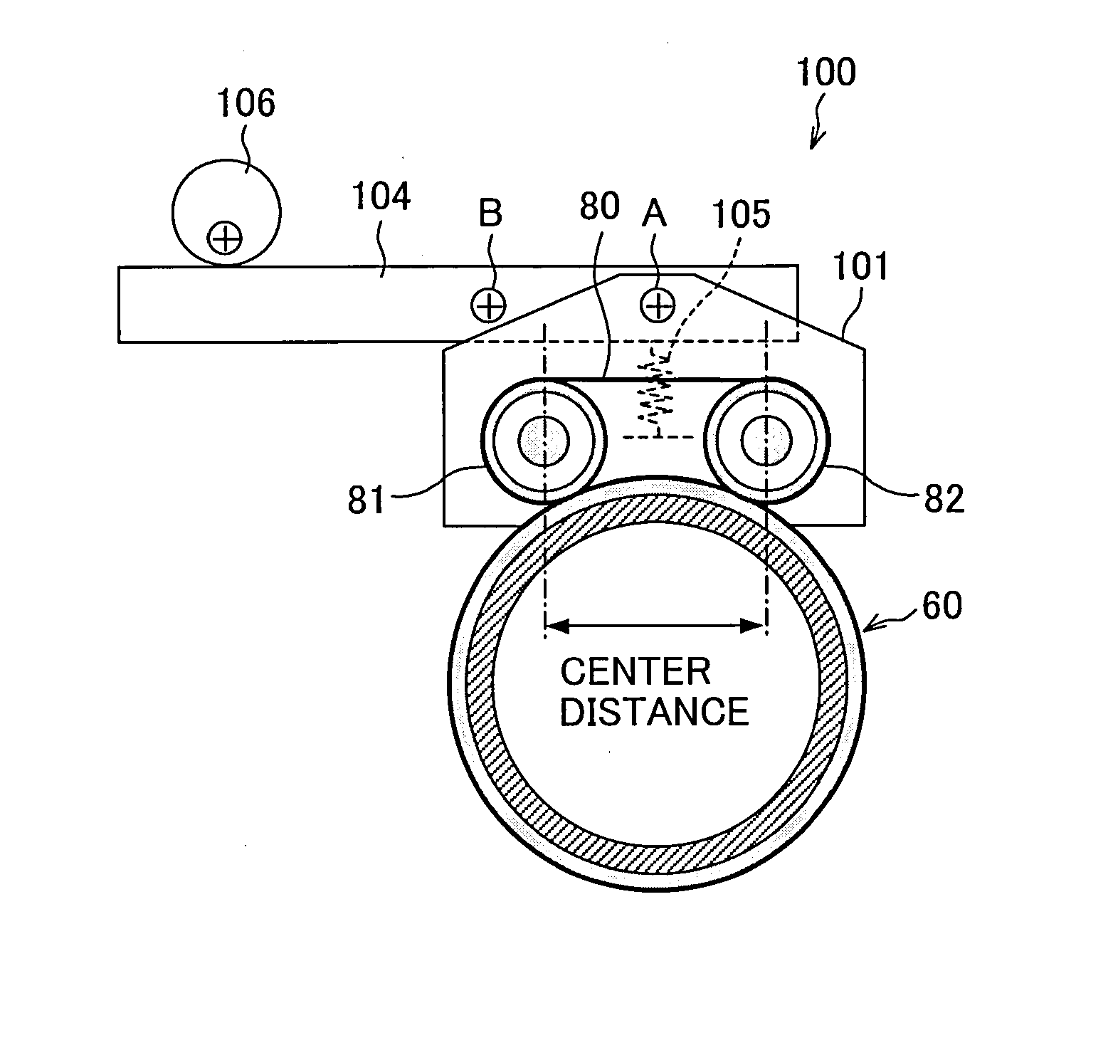
[0106]An image forming apparatus of the present embodiment differs from the image forming apparatus 1 of the First Embodiment only in the arrangement of the release / contact mechanism by which the heat rollers 81 and 82 are separated from or brought into contact with the surface of the fixing roller 60 in the fixing apparatus 40. As such, the following description deals with only the release / contact mechanism.

[0107]FIGS. 6(a) and 6(b) are diagrams illustrating a structure of a support section for the external heating section 75. FIG. 4 is an upper view of the support section. A release / contact mechanism 200 is provided in the support section.

[0108]The release / contact mecha...

third embodiment

[0110]The following will describe another embodiment of the present invention with reference to FIG. 8. Note that, constituting members having the same functions as those described in the foregoing First and Second Embodiments are given the same reference numerals and explanations thereof are omitted here.

[0111]An image forming apparatus of the present embodiment differs from the image forming apparatus 1 of the First Embodiment only in the arrangements of the external heating section and the release / contact mechanism in the fixing apparatus 40. As such, the following description only deals with the external heating section and the release / contact mechanism.

[0112]FIGS. 8(a) and 8(b) are diagrams illustrating a structure of a support section for an external heating section 76. A release / contact mechanism 300 is provided in the support section.

[0113]Instead of the heat roller 82, the external heating section 76 includes a support roller (pressing member) 87 that is not provided with t...


PUM


Abstract

In a fixing apparatus and an image forming apparatus of the present invention, an external heating section is provided that includes: an external heating belt; two heat rollers suspending the external heating belt and pressed against a fixing roller via the external heating belt; and a release/contact mechanism for causing the two heat rollers to separate from or contact with the fixing roller. With the heat rollers separated from the fixing roller by the release/contact mechanism, the external heating belt and the fixing roller are in contact with each other and the external heating belt follows rotation of the fixing roller. As a result, a fixing apparatus is provided that includes an external release/contact mechanism that can quickly operate in a small space and at low power without encouraging deterioration of the belt member. An image forming apparatus provided with such a fixing apparatus is also provided.

Description

[0001]This Nonprovisional application claims priority under 35 U.S.C. § 119(a) on Patent Application No. 070913 / 2006 filed in Japan on Mar. 15, 2006, the entire contents of which are hereby incorporated by reference.FIELD OF THE INVENTION[0002]The present invention relates to a fixing apparatus for fixing a toner image onto a printing medium, and an image forming apparatus provided therewith.BACKGROUND OF THE INVENTION[0003]Image forming apparatuses of the electrophotographic system, such as copying machines, printers, and multi-functional apparatuses (multi-functional printers) generally use a fixing apparatus employing a heat roller fixing method. The fixing apparatus includes a fixing roller and a pressure roller, which are pressed against each other. Both of or one of the fixing roller and the pressure roller are heated to a predetermined surface temperature (fixing temperature) with a heat source (for example, halogen lamp) provided inside. Printing paper with an unfixed toner ...

Claims


Application Information

Patent Timeline
Patent Type & Authority Applications(United States)
IPC IPC(8): G03G15/20
CPCG03G15/2064G03G2215/2019G03G2215/2016
Inventor YAMANA, SHINJIASAKURA, KENJIKAGAWA, TOSHIAKIYAMAJI, HIROYUKI
Owner SHARP KK
Why Eureka
Try Eureka