Exhaust system for gaseous film cooling central cone of turbofan aircraft engine

An exhaust system and film cooling technology, which is applied in the direction of machines/engines, jet propulsion devices, etc., can solve the problems of low mixing efficiency of annular mixers, high temperature and large proportion of hot exhaust gases in exhaust systems, etc.

Inactive Publication Date: 2011-04-27
NANJING UNIV OF AERONAUTICS & ASTRONAUTICS
View PDF7 Cites 30 Cited by
  • Summary
  • Abstract
  • Description
  • Claims
  • Application Information

AI Technical Summary

Problems solved by technology

From the perspective of infrared suppression of the engine exhaust system, this structure has the following disadvantages: (1) The mixing efficiency of the annular mixer is low, and the mixing degree of the internal and external gases of the engine is poor, so the hot exhaust temperature of the exhaust system High, which is detrimental to reducing the infrared radiation of the hot exhaust of the engine; (2) The high-temperature components inside the exhaust system (such as: central cone, flame stabilizer) have not taken cooling measures, and the infrared radiation of these high-temperature components can pass through the exhaust The inner cavity of the system propagates backwards, and the infrared radiation of this part accounts for a large proportion of the overall infrared radiation of the exhaust system, and the radiation is strong
However, this technical measure can only reduce the surface temperature of part of the central cone of the turbofan exhaust system, and the reduction is limited.

Method used


Image

  • Exhaust system for gaseous film cooling central cone of turbofan aircraft engine
  • Exhaust system for gaseous film cooling central cone of turbofan aircraft engine
  • Exhaust system for gaseous film cooling central cone of turbofan aircraft engine

Examples


Embodiment Construction

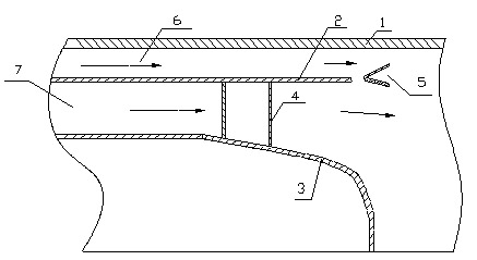
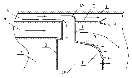
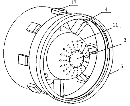
[0013] Such as figure 2 , image 3 and Figure 4 As shown, the outer culvert gas passes through 8 deflectors, and part of the outer culvert cold air enters the center cone rear cavity 10 through 8 hollow turbine rear support plates 4, and the cold air flows out from many small holes arranged on the surface of the center cone. The surface of the cone has a significant cooling effect. A model test study was carried out on the illustrated structure. The test conditions are: the gas flow rate in the inner channel is 0.9kg / s, and the temperature is 893K; the gas flow rate in the outer channel is 0.72 kg / s, and the outer temperature is 305K. The surface temperature of the central cone was measured with a thermal couple, and the backward infrared radiation intensity of the exhaust system was measured with a Fourier spectroradiometer. The test results show that the use of the air film cooling center cone proposed in this patent can reduce the surface temperature of the center con...


PUM


Abstract

The invention discloses an exhaust system for a gaseous film cooling central cone of a turbofan aircraft engine, belonging to the technical field of turbofan aircraft engines. The system sequentially comprises an exhaust system cylinder body (1) of the engine, a confluence ring (2) and a central cone (3) from inside to outside and is characterized in that a central cone end plate (8) is arranged inside the central cone (3); an inner cavity of the central cone is divided into two independent cavities by the central cone end plate, respectively including a central cone front cavity (9) and a central cone rear cavity (10); a gaseous film hole (11) is arranged on the wall surface of the central cone rear cavity; a hollow turbine rear support plate (4) is provided with a hollow cavity which is respectively communicated with an external culvert channel (6) and the central cone rear cavity (10); and a deflector (12) is arranged at the part of the hollow turbine rear support plate (4), which is communicated with the external culvert channel (6). According to the invention, the caudal infrared radiation of the exhaust system can be greatly reduced by reducing the surface temperature of the central cone body.

Description

[0001] technical field [0002] The invention relates to a gas film cooling central cone exhaust system of a turbofan aero-engine, and belongs to the technical field of turbofan aero-engine exhaust system design and infrared suppression. Background technique [0003] Turbofan aero engine exhaust system is an important part of aero engine. Generally, it consists of an annular mixer, a central cone, an afterburner, a flame stabilizer, and an exhaust nozzle. Its function is: to mix the internal and external airflow of the engine, and under the adjustment and control of the geometric area of ​​the exhaust nozzle, the pressure potential energy of the hot exhaust gas can be fully converted into the exhaust kinetic energy to generate thrust; when the afterburner is working, the additional Fuel is injected into the afterburner chamber where it mixes with hot exhaust gas and burns to increase engine thrust. Most of the current turbofan aero-engine exhaust system structure and worki...

Claims


Application Information

Patent Timeline
Patent Type & Authority Applications(China)
IPC IPC(8): F02K1/38F02K3/04
Inventor 张靖周单勇潘丞雄
Owner NANJING UNIV OF AERONAUTICS & ASTRONAUTICS
Why Eureka
Try Eureka