Pipe gripping ram

a technology of gripping rams and pipes, which is applied in the direction of drilling accessories, fluid removal, borehole/well accessories, etc., can solve the problem of taking several hundred foot-pounds of torque to break the connection between sections of pipes

Inactive Publication Date: 2007-03-29
LESKO GERALD
View PDF7 Cites 48 Cited by
  • Summary
  • Abstract
  • Description
  • Claims
  • Application Information

AI Technical Summary

Benefits of technology

[0010] The pipe-gripping tong mounted on the second end of the annular piston comprises a tong shoe and a tong die mounted within the shoe. The tong die has two surfaces with teeth for gripping a pipe. The two surfaces are at an angle to one another to form a shallow v-shaped groove. The shoe has a partial circular opening that allows the tong die to slide into the shoe and be secured by retainer ears mounted on top and bottom of the tong shoe. The tong shoe opening is slightly wider than the tong die such that the tong die has a small amount of side-to-side lateral movement within the shoe thereby allowing the tong die to self-center on a pipe in the event that the pipe is not exactly centered within the jaws of the live head or dead head tongs.

Problems solved by technology

Automated iron roughnecks are used on drilling rigs to perform the often dangerous tasks of making and breaking joints between sections of drilling pipe.
Depending on the diameter of the pipe used in the drill string and the amount of force used in turning the drill string to drill a hole, it may take several hundreds of foot-pounds of torque to break a connection between sections of pipe.

Method used


Image

  • Pipe gripping ram
  • Pipe gripping ram
  • Pipe gripping ram

Examples


Embodiment Construction

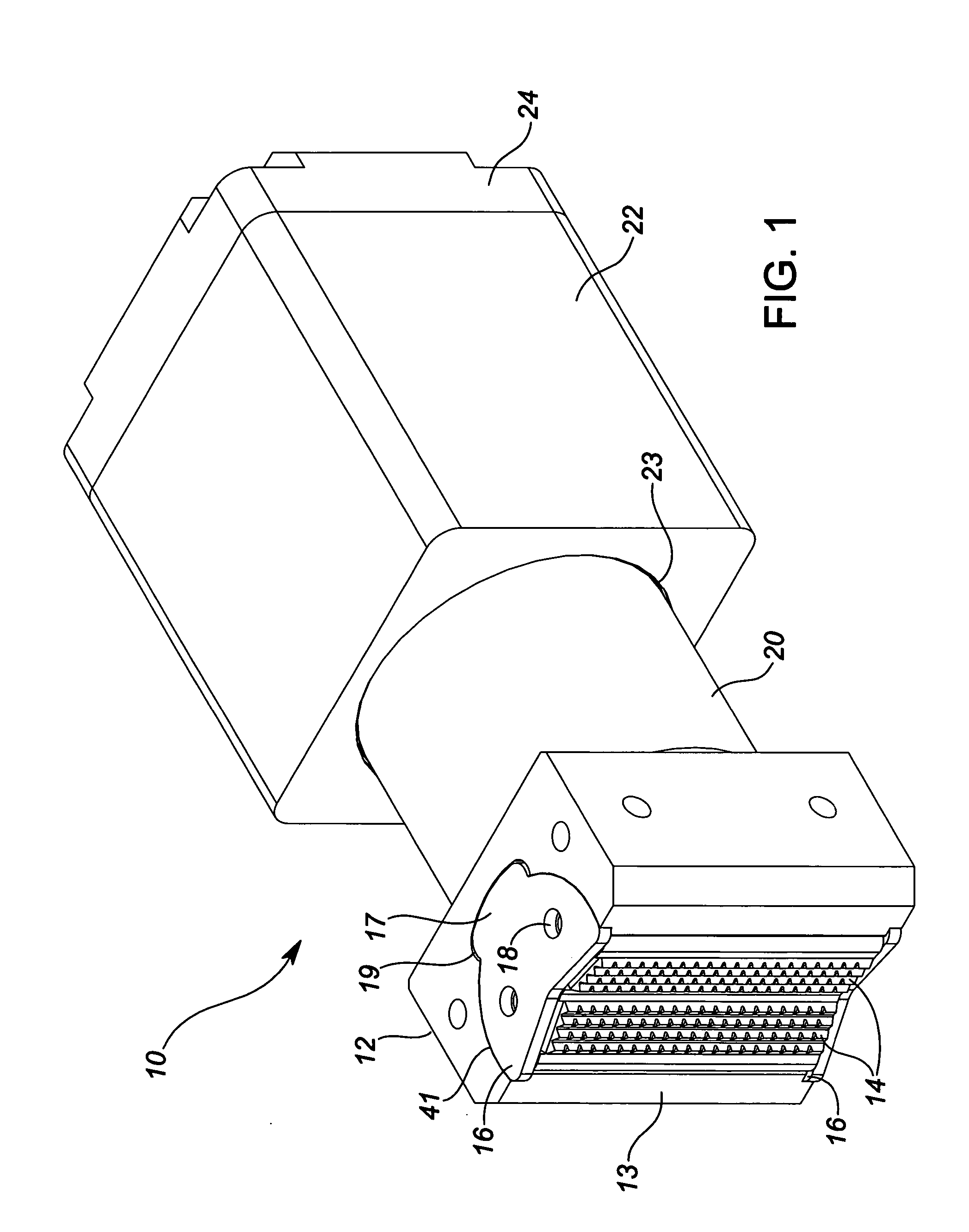
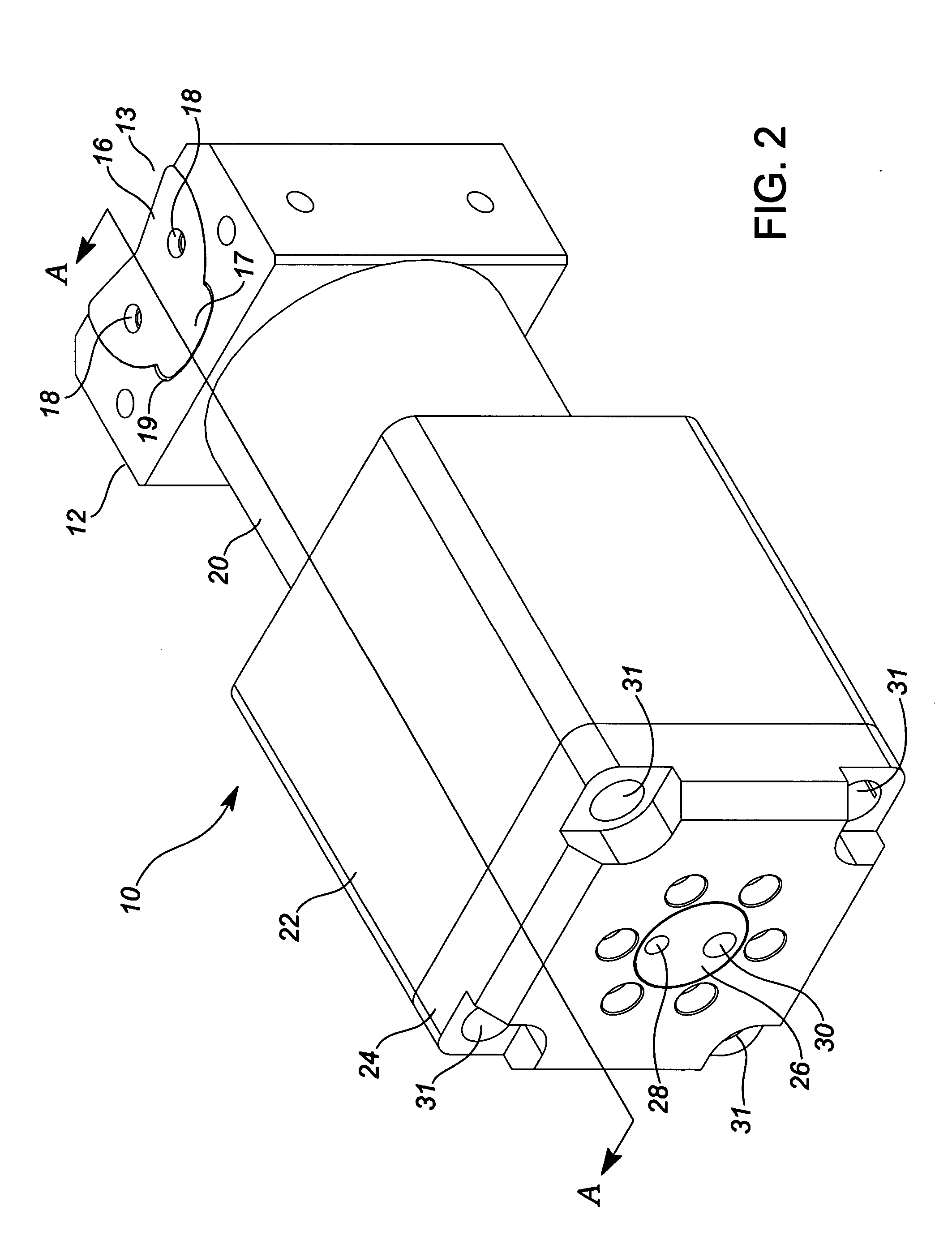
[0019] Referring to FIGS. 1 and 2, a representative embodiment of the present invention is shown. Ram 10 comprises a cylinder block 22, end cap 24, annular piston 20 and tong shoe 12. End cap 24 is fastened to cylinder block 22 by cap screws passing through bolt holes 31. Annular piston 20 slides in and out of bore 23 and cylinder block 22. Tong shoe 12 has a circular opening 41 to receive tong die 13. Tong die retainers 16 are fastened to the top and bottom of tong die 13 to keep it in place within shoe 12. Tong die 13 comprises a pair of die faces 14. Die faces 14 form a shell v-shaped groove for receiving a section of pipe to grip.

[0020] Tong shoe 12 further comprises grooves 19 to receive retainer ear 17 of retainers 16. Groove 19 is slightly wider than ear 17 so as to allow tong die 13 to move laterally side-to-side within opening 41. A combination of shallow v-shaped groove faces 14 and the side-to-side movement of tong die 13 allows tong die 13 to self-center on a section of...


PUM


Abstract

A ram is provided for use in the live and dead heads of an iron roughneck. The ram grips sections of pipe as connections are made or broken between the pipe sections. The ram includes a cylinder block having a bore and a fixed piston centered therein forming an annulus. An annular piston slides in and out of the cylinder block in the annulus. A tong mounted on the end of the end of the annular piston for gripping pipe includes a tong shoe and a tong die within the shoe. The tong die is capable of moving side-to-side within the shoe to self-center itself when gripping pipe. Pressurized gas or hydraulic fluid systems can be used to extend and retract the annular piston within the cylinder block.

Description

FIELD OF THE INVENTION [0001] The present invention relates to the field of rams for gripping drilling pipe. More specifically, the present invention relates to pipe gripping rams on automated iron roughnecks used on drilling rigs. BACKGROUND OF THE INVENTION [0002] Automated iron roughnecks are used on drilling rigs to perform the often dangerous tasks of making and breaking joints between sections of drilling pipe. An iron roughneck usually has two sets of jaws with pipe gripping tongs positioned in a vertical configuration, one on top of the other. The lower set of jaws or “dead head” holds the box end of the section of pipe connected to the drill string. The upper set of jaws or “live head” grasps the pin end of the section of pipe being joined to or removed from the drill string. The dead head tongs hold the drill string steady while the live head tongs turn the pin end of the pipe section clockwise to make a pipe connection or counter-clockwise to break a pipe connection. Depe...

Claims


Application Information

Patent Timeline
Patent Type & Authority Applications(United States)
IPC IPC(8): E21B19/18
CPCE21B19/163
Inventor LESKO, GERALD
Owner LESKO GERALD
Why Eureka
Try Eureka