Color scintillator and image sensor

a color scintillator and image sensor technology, applied in the field of color scintillators and image sensors, can solve the problems of reducing resolution, unable to meet conflicting requirements, and configuration or structure of color scintillators or photosensors, and achieve the effect of less radiation dosage and less light intensity

Inactive Publication Date: 2007-03-29
KK TOSHIBA
View PDF3 Cites 14 Cited by
  • Summary
  • Abstract
  • Description
  • Claims
  • Application Information

AI Technical Summary

Benefits of technology

[0025] The present invention has been achieved to meet such a demand and an object of the present invention is to provide a color scintillator converting electromagnetic waves and radial rays which vary in type or energy to visible lights more simultaneously and effectively with less radiation dosage or less light intensity.

Problems solved by technology

However, in the measurement using such recording media, indirect operations such as development and reading work are required to obtain the internal structure of the objects in the form of image data, resulting in lack of real-time processing.
As a result, the number of light components generated as a result of the reaction with the X-rays E1 is steeply increased with distance from the central portion of the light-emitting portion of the color scintillator toward the outer portion, resulting in a reduction in resolution.
However, configurations or structures of the color scintillator or the photosensor 6 that can satisfy such conflicting requirements have not yet to be invented.
In short, in the known scintillator 5 and image sensors, reduction in resolution is unavoidable when improving the measurement sensitivity as described above.

Method used


Image

  • Color scintillator and image sensor
  • Color scintillator and image sensor
  • Color scintillator and image sensor

Examples


first embodiment

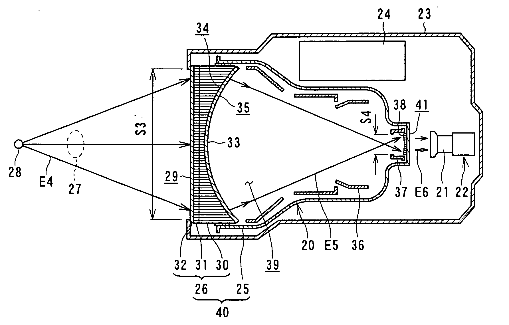
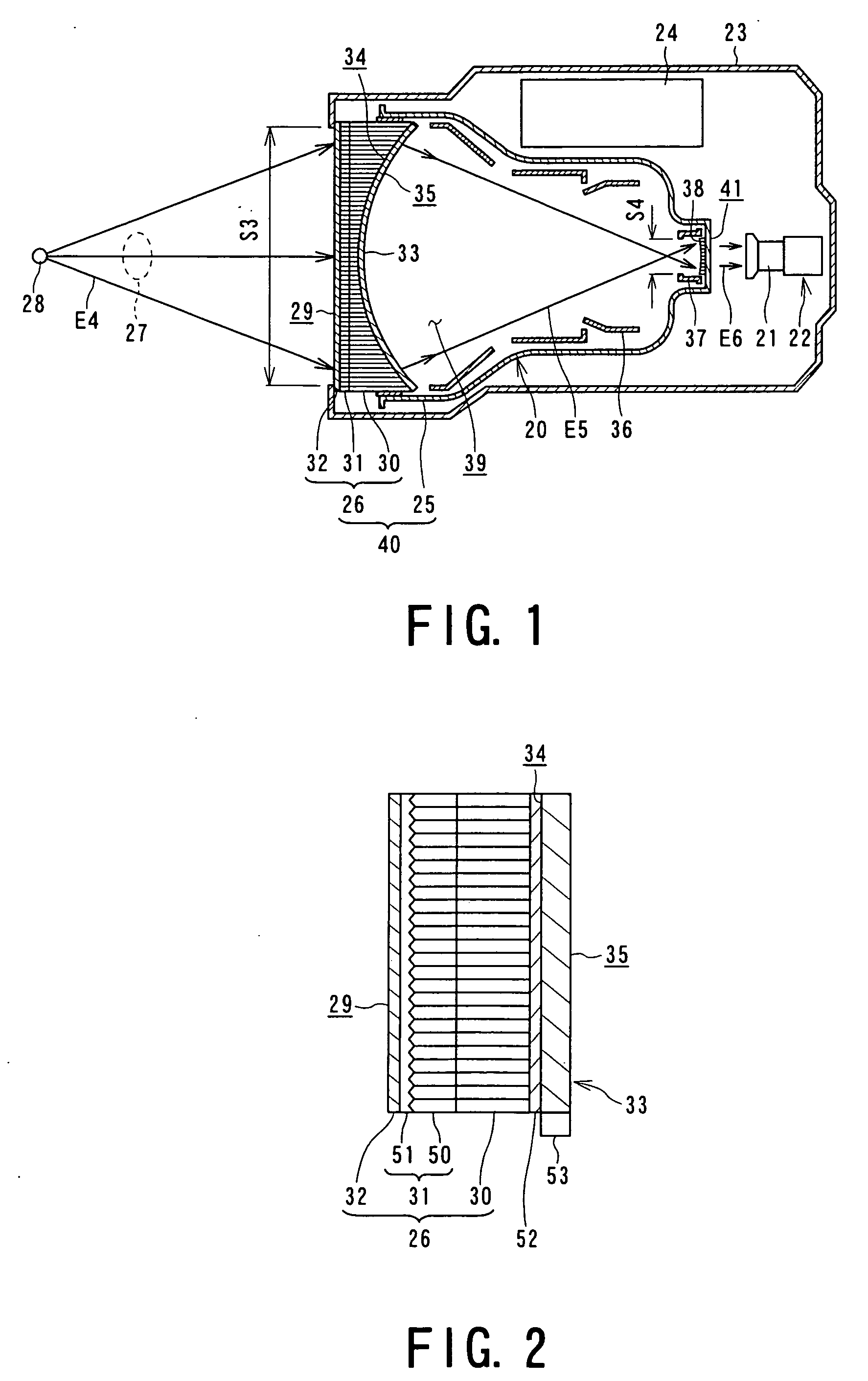
[0039]FIG. 1 is a structural drawing showing an image sensor according to the present invention.

[0040] An image intensifier 201 as an example of image sensors and a color camera 22 including a lens 21 are housed in a tube case 23. The image intensifier 20 includes a high-voltage power supply 24 and a stepped image intensifier tube 25 having a closed end. The opening of the image intensifier tube 25 is closed with a color scintillator 26.

[0041] The color scintillator 26 that closes the opening of the image intensifier tube 25 is arranged at an open end of the tube case 23. E1ectromagnetic waves or radial rays, for example, X-rays E4 emitted from an X-ray tube 28 that is arranged outside the tube case 23 and passing through an object 27, whose images are to be captured enter on a flat incidence face 29 of the color scintillator 26. Thus, the area of the color scintillator 26 facing the exterior of the tube case 23 corresponds to an effective incident area S3 for the X-rays E4.

[0042]...

second embodiment

[0149]FIG. 4 is a structural drawing showing an image sensor according to the present invention.

[0150] In an image sensor 60 shown in FIG. 4, the same numbers as those of the image intensifier 20 shown in FIG. 1 are added to elements equivalent to those of the image intensifier 20.

[0151] An image sensor 60 includes a color scintillator 26 and a color camera 22 arranged inside a camera obscura 61. The camera obscura 61 has an opening, and the color scintillator 26 is arranged at the opening such that an incidence face 29 of the color scintillator 26 faces the exterior of the camera obscura 61 so as to receive X-rays from the exterior of the camera obscura 61.

[0152] The color scintillator 26 includes a lead glass 62 serving as an optical substrate and a scintillator layer 31 arranged thereon. The boundary face between the lead glass 62 and the scintillator layer 31 is flat. Furthermore, the other face of the scintillator layer 31 remote from the lead glass 62 is flat, and is protect...


PUM


Abstract

A color scintillator 26 comprises: an optical substrate 30 having bundled optical fibers; an acicular scintillator 50 provided with the optical substrate 30, the acicular scintillator having either of an acicular crystal structure and a columnar crystal structure, the acicular scintillator reacting with at least one of an electromagnetic wave and a radial ray into light emitting; and a coating scintillator 51 coating the acicular scintillator 50, the coating scintillator reacting with at least one of another electromagnetic wave and another radial ray which differ in either of an energy and a type from the electromagnetic wave and the radial ray reacting with the acicular scintillator 50 into light emitting in a different color from an emitting color in the acicular scintillator 50.

Description

TECHNICAL FIELD [0001] The present invention relates to a color scintillator converting electromagnetic waves and radial rays which vary in type or energy to visible lights identifiably and an image sensor generating images using visible lights converted by a color scintillator. BACKGROUND ART [0002] When radial rays such as X-rays and γ-rays pass through objects, the absorption and dispersion of the radial rays in the objects vary according to the shapes of the objects through which the radial rays pass through and the varieties of the materials of the objects. By means of this characteristic, information such as broken states, changes, and filling states inside the objects can be obtained by measuring the strengths of the radial rays that pass through the objects. The strengths of these radial rays are visualized and recorded with recording means such as photography, video recording, and digital files. [0003] Methods for observing states inside objects or samples without destroyin...

Claims


Application Information

Patent Timeline
Patent Type & Authority Applications(United States)
IPC IPC(8): G01T1/20
CPCG01T1/20G01T1/2008
Inventor NITTOH, KOICHINAKAYAMA, KUNIHIKOKITSUKAWA, KEISUKEABE, MOTOHISANOJI, TAKASHI
Owner KK TOSHIBA
Why Eureka
Try Eureka