Method for compensating an image

a compensation method and image technology, applied in the field of digital devices, can solve problems such as unfavorable acquisition of image information

Active Publication Date: 2007-03-29
SAMSUNG ELECTRONICS CO LTD
View PDF5 Cites 14 Cited by
  • Summary
  • Abstract
  • Description
  • Claims
  • Application Information

AI Technical Summary

Benefits of technology

[0011] In accordance with an aspect of the present invention, there is provided a method for compensating an image in image means for implementing image information, by taking account of ambient illumination. Measurement is made of luminance of the external background illuminat...

Problems solved by technology

Although recent digital devices are highly integrated to achieve small size, be lightweight, and offer multiple functions, and provide users with the convenience of various information and functions the user, problematically, does not acquire, o...

Method used


Image

  • Method for compensating an image
  • Method for compensating an image
  • Method for compensating an image

Examples


first embodiment

[0052]FIG. 4 is a block diagram illustrating steps of the second to fourth processes in accordance with the present invention. Next, the step of compensating chroma of an image will be described. Tristimulus values X, Y, and Z of the image can be computed from an intensity of the background illumination (410 and Table 1). X and Z of the computed tristimulus values can be transformed to a*b* according to the CIELAB color space (420). Y indicates luminance of the image (440) and varied luminance Y′ is computed (450). Y′ can be transformed to L* according to the CIELAB color space.

[0053] After L*a*b* based on the CIELAB color space is combined, a combination result is reflected to image compensation.

[0054]FIG. 7 is a graph illustrating chroma variation according to a flare phenomenon and a chroma enhancement method. The x-axis of the graph represents chroma, and the y-axis of the graph represents luminance. Polygonal graphs represent a color boundary, respectively. The color boundary ...

second embodiment

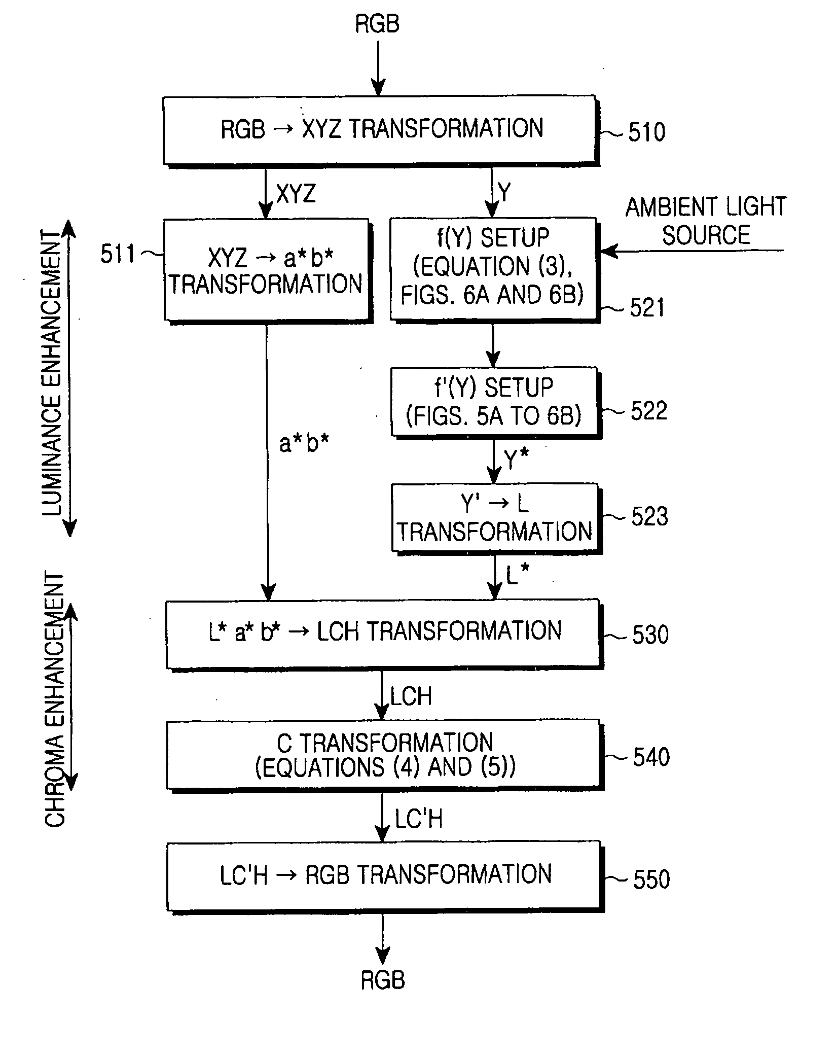
[0057]FIG. 8 is a block diagram illustrating an algorithm in accordance with the present invention. Referring to FIG. 10, the luminance and chroma improvements in accordance with this embodiment are achieved through two steps. The algorithm transforms data input in a system of three primary colors (RGB) to tristimulus values (Step 510). The tristimulus values X, Y, and Z set a sensitivity curve (associated with Equation (2) and f(Y) of FIGS. 6A and 6B) (Step 521), and the tristimulus values are transformed to a*b* (Step 511).

[0058] The sensitivity curve (associated with f(Y) and FIGS. 5A to 6B) is transformed by a mirror-image inverse function f′(Y) (Step 522). Y′ of the tristimulus values of the inverse function is transformed to L* (Step 523).

[0059] After steps 523 and 511, a*b* and L* are transformed to LCH (Step 530). According to transformation of C, LCH is transformed to LC′H according to Equations (4) and (5) (Step 540). LC′H is transformed to RGB, such that RGB is output.

[...


PUM


Abstract

A method for compensating an image produced by image means for implementing image information takes account of ambient illumination. Luminance of external background illumination around the image means is measured. The measured luminance of the background illumination is compared with preset tristimulus values and a reflectance factor of the image means, a comparison result is computed, and a control signal is generated to compensate luminance and chroma of an image. Luminance and chroma of the image means are compensated in response to the control signal.

Description

CLAIM OF PRIORITY [0001] This application claims priority under 35 U.S.C. § 119 to an application entitled “Method for Compensating an Image,” filed in the Korean Intellectual Property Office on Sep. 29, 2005 and assigned Serial No. 2005-91342, the contents of which are incorporated herein by reference. BACKGROUND [0002] 1. Field of the Invention [0003] The present invention generally relates to a digital device, and more particularly to a digital device with image means that is portable in an outdoor area and can provide information in an image form. [0004] 2. Description of the Related Art [0005] With the development of electronic and digital technologies, digital devices are being supplied in various personal, portable forms, such as a navigation system, personal digital assistant (PDA), portable phone, notebook computer, electronic dictionary, Motion Pictures Experts Group (MPEG) Audio Layer 3 (MP3) digital camcorder, camera, and so on. The digital devices are equipped with imag...

Claims


Application Information

Patent Timeline
IPC IPC(8): G09G5/02G09G5/10G03B7/02G06T1/00G09G3/20G09G3/36H04N1/46H04N1/60H04N5/20H04N9/68
CPCG09G3/2003G09G5/02G09G2320/04G09G2320/0666G09G2340/06H04N21/4318H04N1/6086H04N5/58H04N9/68H04N21/41407H04N21/42202G09G2360/144G09G3/20G09G3/30G09G3/36
Inventor CHO, SUNG-DAEWON, SEOK-JINPARK, JUNG-HOONJEONG, YOUNG-MINMOON, JAE-WONOH, YUN-JEHA, YOUNG-HOKIM, JONG-MANLEE, CHEOL-HEESON, CHANG-HWAN
Owner SAMSUNG ELECTRONICS CO LTD
Why Eureka
Try Eureka