
High zoom ratio zoom lens system

Active Publication Date: 2007-03-29
NIKON CORP
View PDF10 Cites 13 Cited by
  • Summary
  • Abstract
  • Description
  • Claims
  • Application Information

AI Technical Summary

Benefits of technology

[0013] The present invention is made in view of the aforementioned problems and has an object to provide a high zoom ratio zoom lens system having a short total lens length and a small effective diameter of the first lens group in spite of securing superb optical performance, having a half angle of view in the telephoto end state of 3.5 degrees or less, an f-number in the telephoto end state of six or less, and a zoom ratio of about 10 or more.

Problems solved by technology

However, in zoom lens systems disclosed in example 1 to 3 of Japanese Patent Application Laid-Open No. 7-20381, since a normalized total thickness along the optical axis of a first lens group is large, in other words, the total thickness of the first lens group normalized by an image height IH in a wide-angle end state is about 3.7, the weight of glass materials tends to become heavy.
Accordingly, the weight of the optical system tends to increase, and mechanical decentering of the first lens group upon becoming the maximum total lens length, which is in the telephoto end state, also tends to increase, so that it is undesirable.
In zoom lens systems disclosed in Example 4 and 5 of Japanese Patent Application Laid-Open No. 7-20381, although the normalized total thickness along the optical axis of the first lens group is about 2.14, and the maximum effective diameter is 6.7, which are relatively small, there is another problem that variation in spherical aberration upon zooming from the wide-angle end state to the telephoto end state becomes large.
However, there is a problem that the dimension of the first lens group becomes large such that the normalized total thickness of the first lens group is from 3.66 to 4.42, and the maximum effective diameter is from 8.37 to 9.68.

Method used


Image

  • High zoom ratio zoom lens system
  • High zoom ratio zoom lens system
  • High zoom ratio zoom lens system

Examples


example 1

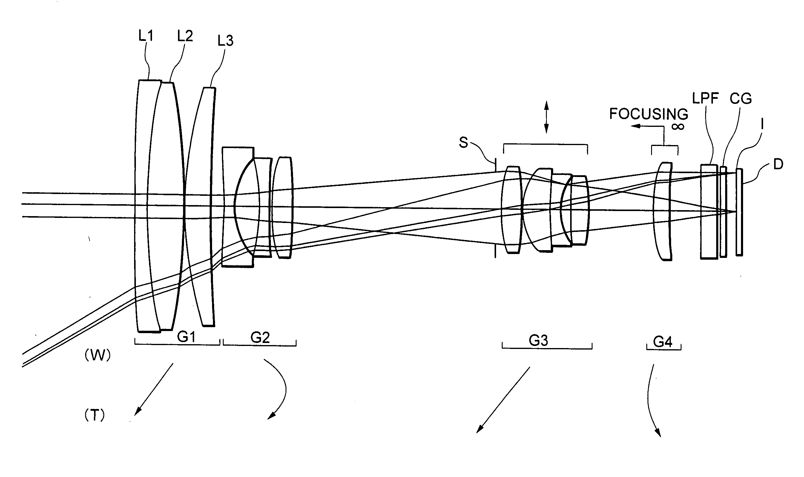
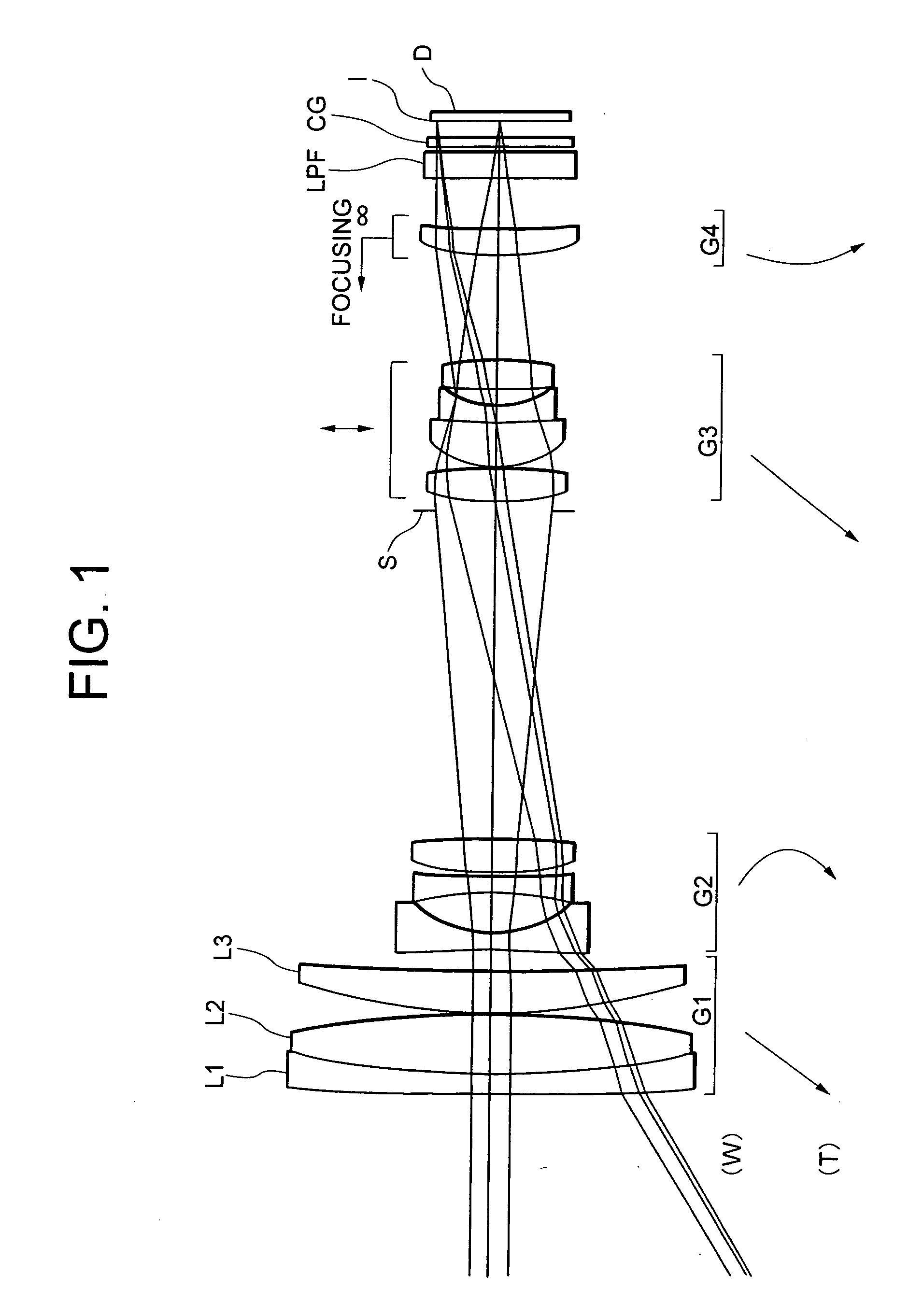
[0076]FIG. 1 is a diagram showing a lens configuration of a high zoom ratio zoom lens system according to Example 1 of the present application and positions of respective lens groups in a wide-angle end state W upon focusing on infinity.

[0077] In FIG. 1, the high zoom ratio zoom lens system according Example 1 is composed of, in order from the object, a first lens group G1 having positive refractive power, a second lens group G2 having negative refractive power, an aperture stop S, a third lens group G3 having positive refractive power, a fourth lens group G4 having positive refractive power, an optical low-pass filter LPF, and a cover glass CG for a solid-state imaging device D.

[0078] The first lens group G1 is composed of, in order from the object, a cemented positive lens constructed by a negative meniscus lens L1 having a convex surface facing the object cemented with a double convex positive lens L2, and a positive meniscus lens L3 having a convex surface facing the object.

[...

example 2

[0092]FIG. 6 is a diagram showing a lens configuration of a high zoom ratio zoom lens system according to Example 2 of the present application and positions of respective lens groups in a wide-angle end state W upon focusing on infinity.

[0093] In FIG. 6, the high zoom ratio zoom lens system according to Example 2 is composed of, in order from the object, a first lens group G1 having positive refractive power, a second lens group G2 having negative refractive power, an aperture stop S, a third lens group G3 having positive refractive power, a fourth lens group G4 having positive refractive power, an optical low-pass filter LPF, and a cover glass CG for a solid-state imaging device D.

[0094] The first lens group G1 is composed of, in order from the object, a cemented positive lens constructed by a negative meniscus lens L1 having a convex surface facing the object cemented with a double convex positive lens L2, and a positive meniscus lens L3 having a convex surface facing the object...

example 3

[0102]FIG. 9 is a diagram showing a lens configuration of a high zoom ratio zoom lens system according to Example 3 of the present application and positions of respective lens groups in a wide-angle end state W upon focusing on infinity.

[0103] In FIG. 9, the high zoom ratio zoom lens system according to Example 3 is composed of, in order from the object, a first lens group G1 having positive refractive power, a second lens group G2 having negative refractive power, an aperture stop S, a third lens group G3 having positive refractive power, a fourth lens group G4 having positive refractive power, an optical low-pass filter LPF, and a cover glass CG for a solid-state imaging device D.

[0104] The first lens group G1 is composed of, in order from the object, a cemented negative lens constructed by a negative meniscus lens L1 having a convex surface facing the object cemented with a double convex positive lens L2, and a positive meniscus lens L3 having a convex surface facing the object...


PUM


Abstract

Providing a high zoom ratio zoom lens system having a short total lens length and a small diameter of the first group despite of securing excellent optical performance, a half angle of view of 3.5° or less in the telephoto end, an f-number of 6 or less in the telephoto end, and a zoom ratio of about 10 or more. The system is composed of a first group having positive power, a second group having negative power, a third group having positive power, and a fourth group having positive power. The first group is composed of, in order from the object, a negative meniscus lens having a convex surface facing the object, a first positive lens having a convex surface facing the object, and a second positive lens. All groups moves along the optical axis upon zooming from a wide-angle end to a telephoto end. Given conditions are satisfied.

Description

[0001] The disclosure of the following priority applications are herein incorporated by reference: [0002] Japanese Patent Application No. 2005-282932 filed on Sep. 28, 2005, and [0003] Japanese Patent Application No. 2006-232162 filed on Aug. 29, 2006. BACKGROUND OF THE INVENTION [0004] 1. Field of the Invention [0005] The present invention relates to a photographic high zoom ratio zoom lens system suitable for an electronic still camera and the like. [0006] 2. Related Background Art [0007] In a photographic high zoom ratio zoom lens system suitable for an electronic still camera and the like, there have been known zoom lens systems carrying out zooming by moving all lens groups thereof, having a zoom ratio of about ten, disclosed in such as Japanese Patent Application Laid-Open No. 7-20381. [0008] Moreover, there have been known high zoom ratio zoom lens systems, in which a first lens group is fixed upon carrying out zooming, and a zoom ratio thereof is extended about twelve to six...

Claims


Application Information

Patent Timeline
IPC IPC(8): G02B15/14
CPCG02B27/646G02B15/173G02B15/144113
Inventor SATO, SUSUMU
Owner NIKON CORP
Learn More