

Interferometer, in particular for determining and stabilizing the relative phase of short pulses
a technology of interferometer and relative phase, which is applied in the direction of optical resonator shape and construction, instruments, laser details, etc., can solve the problems of white light collimation through curved mirrors, phase does not remain constant in amplifiers, and requires a high level of adjustment complexity, so as to prevent “walk off”
- Summary
- Abstract
- Description
- Claims
- Application Information
AI Technical Summary
Benefits of technology
Problems solved by technology
Method used
Image

Examples
Embodiment Construction
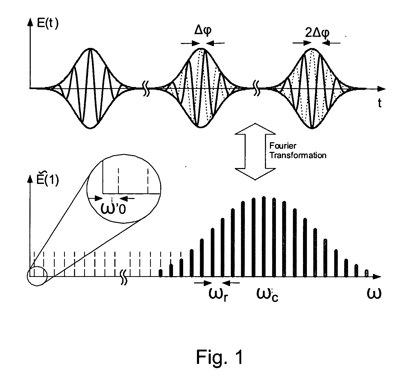
[0034]FIG. 1 illustrates a circulation of a very short pulse in a laser resonator with dispersion. While the envelope moves at the group velocity vg=dω / dk, the carrier phase runs at the phase velocity vp=ω / k, so that, after each cycle, the relative phase between the carrier wave and the envelope increases by an angle Δφ. The spectrum shown in the lower part is obtained through Fourier transformation of the strictly periodic envelope. This spectrum consists of modes spaced apart by the pulse repetition rate ωr, which are shifted by ωo=Δφ / T from the harmonic of ωr, wherein T=2π / ωr represents the pulse cycle time.
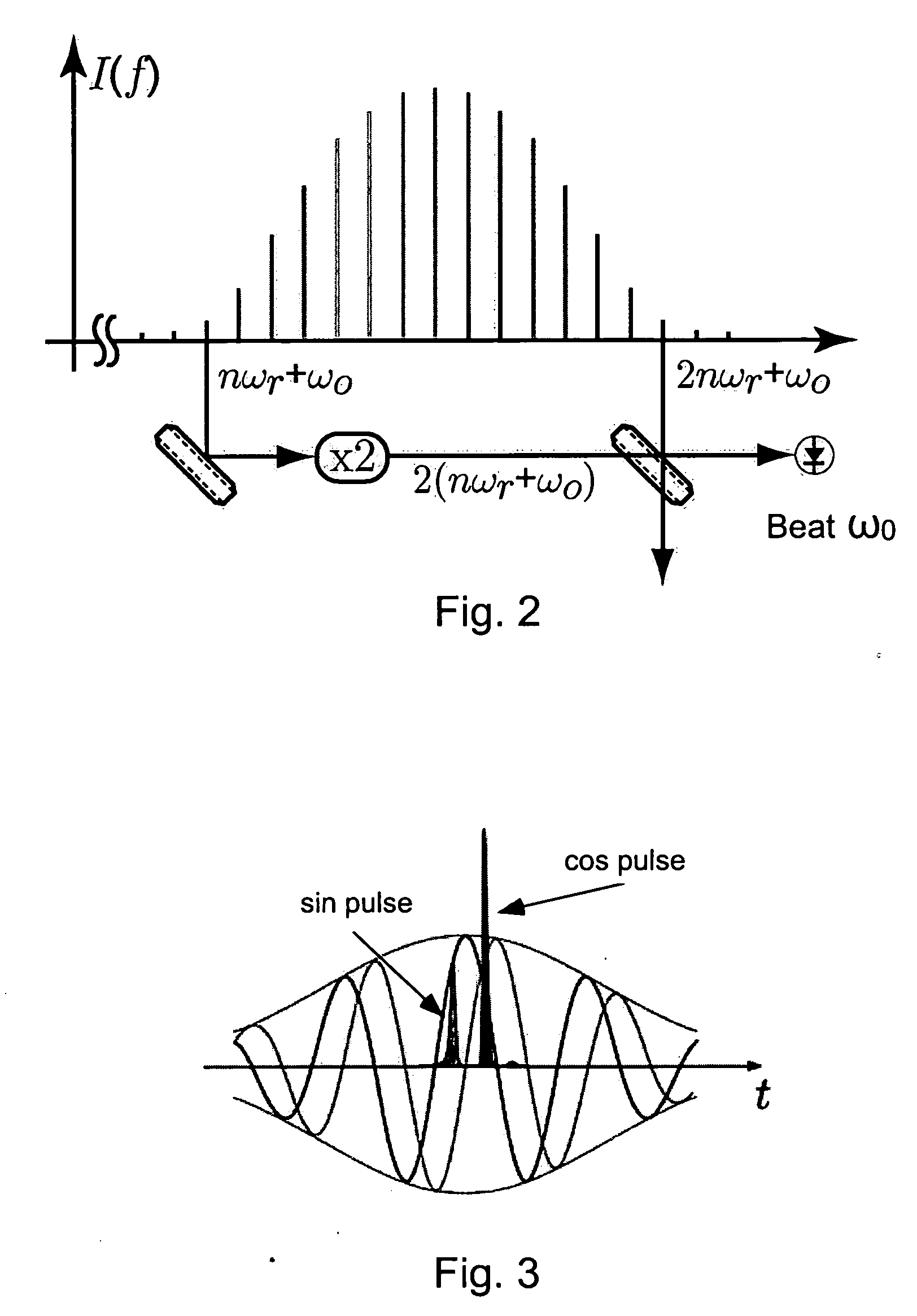
[0035]FIG. 2 shows that a spectrum which covers an entire optical octave which contains two modes with the mode number n and 2n. If the mode with the mode number n has its frequency doubled and is made to beat with the mode 2n, then according to equation 2 the desired frequency is obtained ωo=2(nωr+ωo)−(2nωr+ωo).
[0036]FIG. 3 illustrates the calculated intensity at 3.2 nm and...
PUM
 Abstract
Description
Claims
Application Information