
LED array light source

A technology of LED array and LED substrate, applied in the field of LED array light source, can solve the problems of unfavorable light gathering, low light utilization rate, large light source area, etc.

Pending Publication Date: 2017-08-18
EFUN DISPLAY TECH (SHENZHEN) CO LTD
View PDF5 Cites 0 Cited by
  • Summary
  • Abstract
  • Description
  • Claims
  • Application Information

AI Technical Summary

Problems solved by technology

[0003] The traditional LED array light source mainly adopts a tiled structure. There are tiled LED patches or tiled wafer packaging. The entire array plane is the light-emitting plane. The area of ​​​​the light source is large, which is not conducive to gathering light.
Therefore, when the traditional LED array light source is applied to the occasion of concentrated projection, a large condenser lens is required to collect the light, which is costly, and there is a large amount of scattered light that cannot be used, resulting in low light utilization.

Method used


Image

  • LED array light source
  • LED array light source

Examples


Embodiment Construction

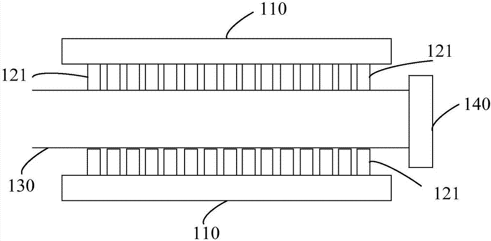
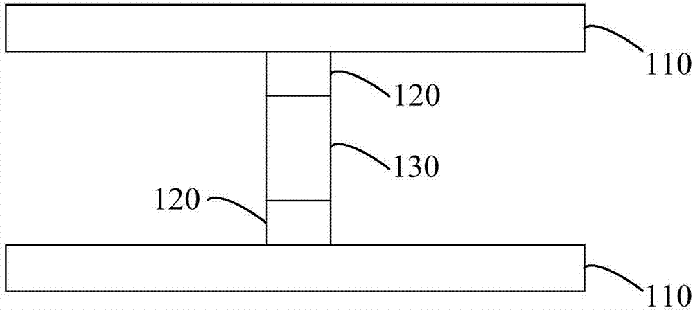
[0010] refer to figure 1 and figure 2 , the LED array light source in one embodiment includes an LED substrate 110 , an LED array 120 , a filter film (not shown in the figure) and a transparent rod 130 . The filter film is arranged on the outer wall of the transparent rod 130; the LED array 120 is fixed on the side of the LED substrate 110 close to the transparent rod 130, electrically connected to the LED substrate 110, and the LED array 120 is arranged on the side of the transparent rod 130 provided with the filter film .

[0011] The light emitted by the LED array 120 enters the transparent rod 130 through the filter film, and the light in the transparent rod 130 is emitted from one end of the transparent rod 130 after being reflected by the filter film.

[0012] The LED substrate 110 is used for the normal operation of the LED array 120 . As a luminous body, the LED array 120 is composed of multiple light-emitting devices, which can be in one row or in multiple rows an...


PUM


Abstract

The invention relates to an LED array light source, comprising LED substrates, LED arrays, a film filter and a transparent rod, wherein the film filter is arranged on the outer wall of the transparent rod, the LED arrays are fixed at the sides, close to the transparent rod, of the LED substrates and are electrically connected with the LED substrates, and the LED arrays are arranged at one side, provided with the film filter, of the transparent rod. Light emitted by the LED arrays enters the transparent rod via the film filter, and the light in the transparent rod is emitted out from one end of the transparent rod after being reflected by the film filter. Therefore, all light emitted by the LED arrays can be concentrated to form a point light source with a small light emission area so as to avoid light scattering, and the light utilization rate is high. The LED array light source can be applied to an occasion of concentrated projection, and is convenient to use and low in cost.

Description

technical field [0001] The invention relates to the field of optoelectronic technology, in particular to an LED array light source. Background technique [0002] LED (Light-Emitting Diode light-emitting diode) array light source adopts light-emitting diodes in the form of an array as the illuminant, which has the advantages of high luminous efficiency, low power consumption, long service life and environmental protection, and is widely used in lighting. [0003] The traditional LED array light source mainly adopts a tiled structure, which is in the form of tiled LED patches or tiled wafer packaging. The entire array plane is the light-emitting plane, and the area of ​​the light source is large, which is not conducive to gathering light. Therefore, when the traditional LED array light source is applied to the occasion of concentrated projection, a large condenser lens is required to collect the light, which is costly, and there is a large amount of scattered light that cannot...

Claims


Application Information

Patent Timeline
IPC IPC(8): F21K9/20F21V9/16F21K9/64F21Y115/10
Inventor 唐文天
Owner EFUN DISPLAY TECH (SHENZHEN) CO LTD
Learn More