
Optical pickup, optical disc device and method for manufacturing optical pickup
a manufacturing method and optical pickup technology, applied in the manufacture of optical heads, instruments, data recording, etc., can solve the problems of degrading the recording/playback characteristics of optical disks, complicated and enlarged optical pickups, and not applying fine adjustment methods to thin-type optical pickups. , to achieve the effect of simple configuration
- Summary
- Abstract
- Description
- Claims
- Application Information
AI Technical Summary
Benefits of technology
Problems solved by technology
Method used
Image

Examples
Embodiment Construction
[0024]One embodiment of the present invention will be described in detail with reference to the accompanying drawings.
(1) Overall Configuration of Optical Disk Apparatus
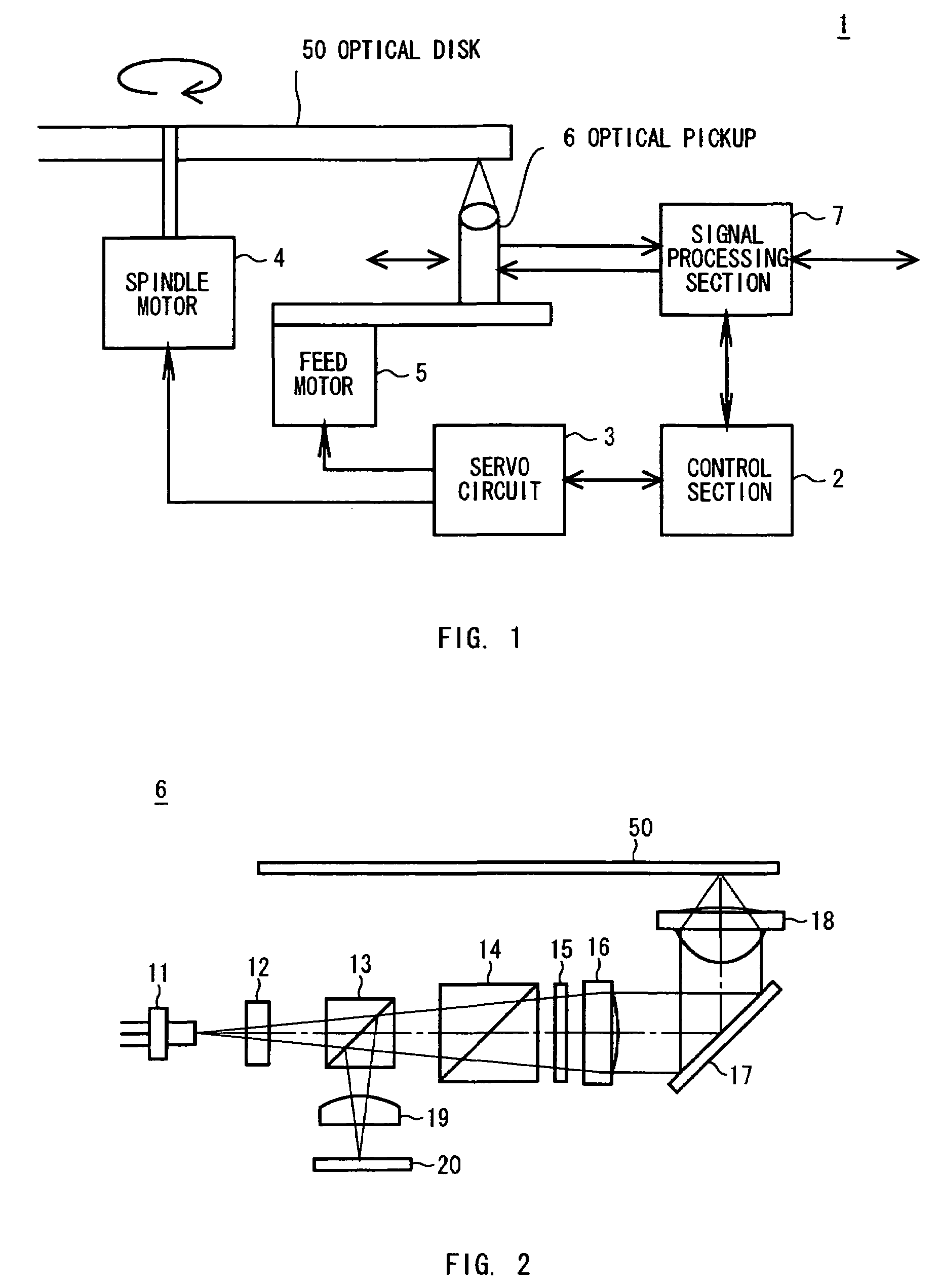
[0025]In FIG. 1, a reference numeral 1 denotes an optical disk apparatus and a control section 2 controls each part of the optical disk apparatus 1.
[0026]That is, the control section 2 rotates a spindle motor 4 through a servo circuit 3 and rotatingly drives an optical disk 50 placed on a turn table (not illustrated). Moreover, the control section 2 rotates a feed motor 5 through the servo circuit 3 and moves an optical pickup 6 in the radial direction of the optical disk 50. Furthermore, the control section 2 controls a signal processing section 7 and executes data read / write from and into the optical disk 50.
[0027]Besides, the control section 2 controls a lens drive of the optical pickup 6 and drives the objective lens of the optical pickup 6 in the tracking direction and the focus direction.
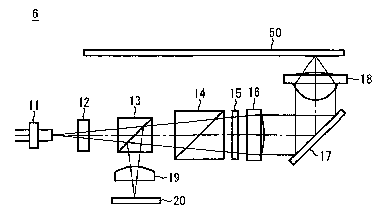
[0028]FIG. 2 illustrate...
PUM
| Property | Measurement | Unit |
|---|---|---|
| rotational angle | aaaaa | aaaaa |
| rotational angle | aaaaa | aaaaa |
| mounting angles | aaaaa | aaaaa |
Abstract
Description
Claims
Application Information