
Transcoder and transcoding method operating in a transform domain for video coding schemes possessing different transform kernels

a transform domain and video coding technology, applied in the field of video transcoding apparatus and methods, can solve the problems of non-trivial transcoding problem, non-trivial transcoding problem, and complex transcoding architecture, so as to save computational cost, simplify the transcoding architecture, and reduce computation complexity

Inactive Publication Date: 2007-03-29
AVISONIC TECH
View PDF1 Cites 32 Cited by
  • Summary
  • Abstract
  • Description
  • Claims
  • Application Information

AI Technical Summary

Benefits of technology

This patented technology simplifies how video signals are converted from one format to another. It does this by combining two operations: down-sampling and transformation. By doing both at once, it reduces the amount of work needed and makes the process more efficient. Also, by making use of certain calculations made during the first step, subsequent steps can be done faster without having to repeat them all over again. Overall, this results in better performance and lower costs for converting videos to different formats.

Problems solved by technology

The technical problem addressed in this patent text relates to developing methods for efficiently transferring videos from one format to another without compromising their quality. Specifically, it focuses on the challenge of adapting to the high level of compression introduced by the H.264 standard compared to older standards like MPEG-2.

Method used


Image

  • Transcoder and transcoding method operating in a transform domain for video coding schemes possessing different transform kernels
  • Transcoder and transcoding method operating in a transform domain for video coding schemes possessing different transform kernels
  • Transcoder and transcoding method operating in a transform domain for video coding schemes possessing different transform kernels

Examples


first embodiment

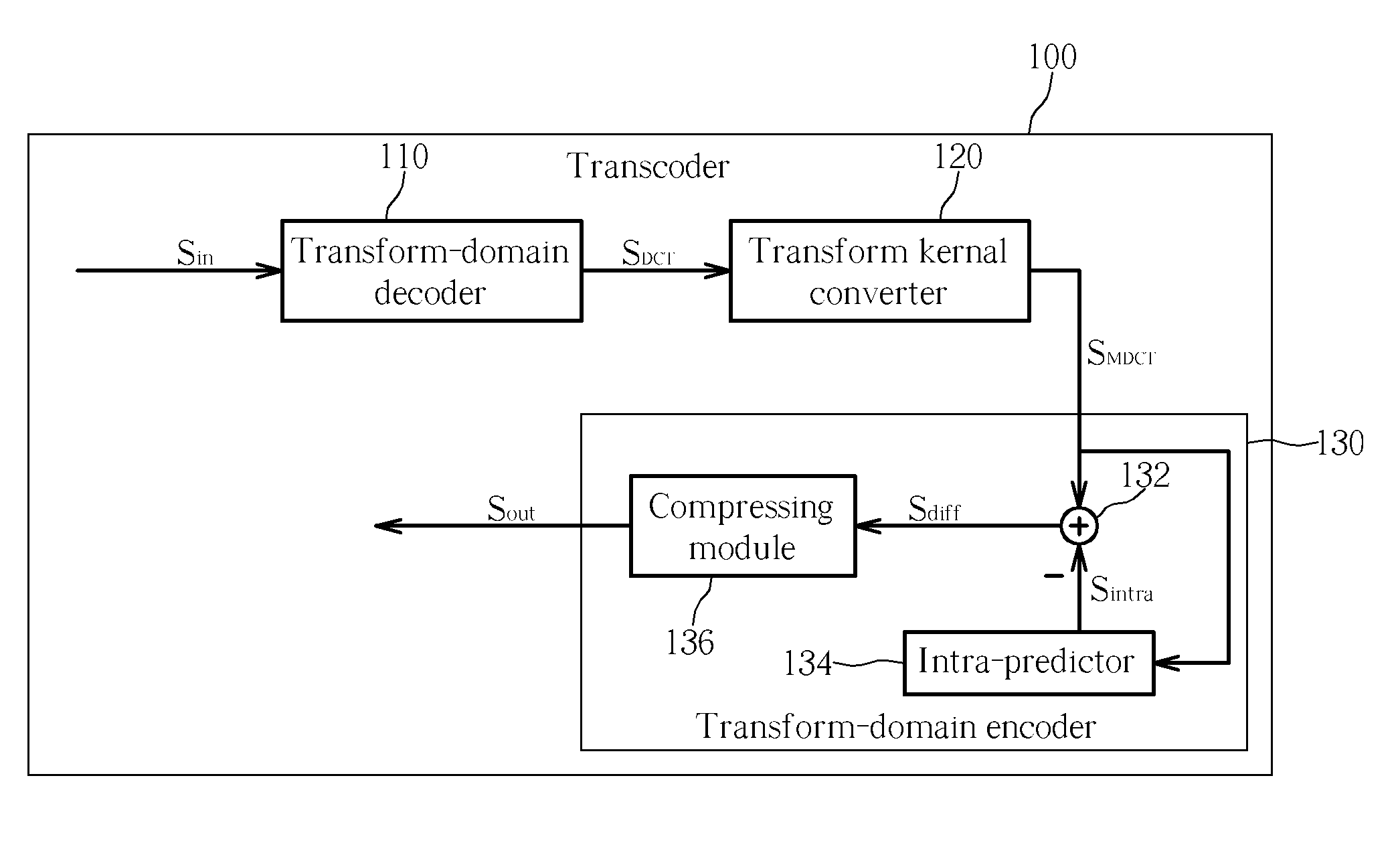
[0018] Please refer to FIG. 1. FIG. 1 is a block diagram illustrating a transcoder 100 for I-frame according to the present invention. In this embodiment, assume that a digital video signal Sin, which is an input signal of the transcoder 100, complies with the MPEG-2 specification and a resultant video signal Sout, which is an output signal of the transcoder 100, complies with the H.264 specification. It is well known that MPEG-2 and H.264 specifications both are block-based video coding schemes. Please note that an image content represented in pixel values is compressed and encoded to comply with MPEG-2 standard by firstly performing a discrete cosine transform (DCT) operation on the image content to generate a DCT-domain image content. Then the DCT-domain image content is further compressed or encoded to fully comply with MPEG-2 specification. The transcoder 100 in FIG. 1 only illustrates an I-frame (intra frame) transcoding architecture.

[0019] In the transcoder 100, when the digi...

second embodiment

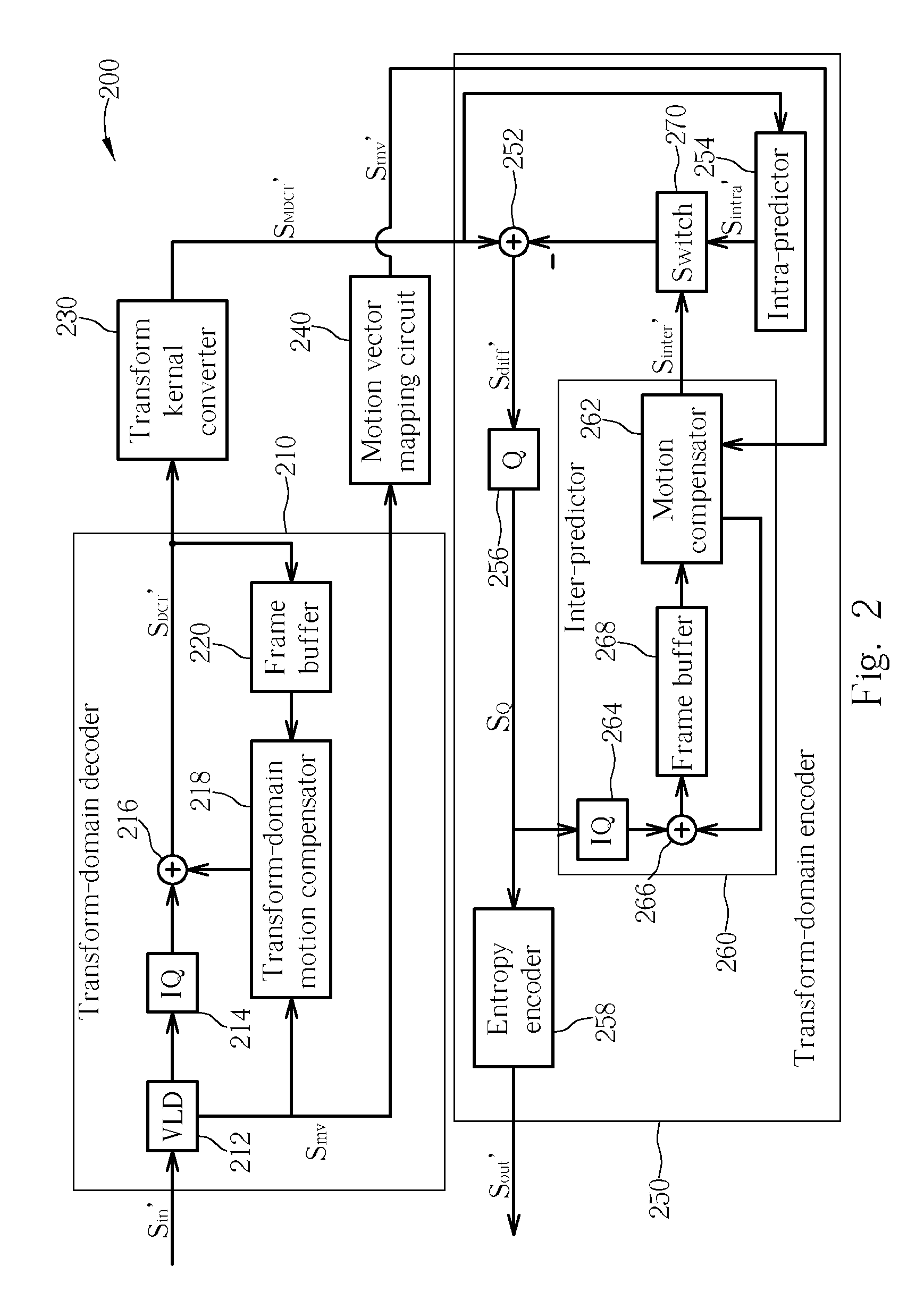
[0022] Please refer to FIG. 2. FIG. 2 is a block diagram illustrating a transcoder 200 for both I-frame and P-frame (inter frame) according to the present invention. For both I-frame and P-frame, the transcoder 200 utilizes a transcoding scheme for transcoding an MPEG-2 video signal (digital video signal Sin′) to an H.264 video signal (resultant video signal Sout′). The transcoder 200 includes a transform-domain decoder 210, a transform kernel converter 230, a motion vector mapping circuit 240, and a transform-domain encoder 250. The transform-domain decoder 210 contains a variable-length decoder (VLD) 212, an inverse quantizer (IQ) 214, an adder 216, a transform-domain motion compensator 218, and a frame buffer 220. A feedback loop consisted of the adder 216, the transform-domain motion compensator 218, and the frame buffer 220 is utilized to recover a P-frame in the transform domain. Since functionality and operation of the VLD 212, IQ 214, and the feedback loop is well known to t...


PUM


Abstract

A transcoder for converting a digital video signal from a first format into a second format in transform domain. The first format and the second format are respectively adopted by video coding schemes possessing different DCT transform kernels. The transcoder includes: a transform-domain decoder, coupled to the digital video signal, for decoding the digital video signal of the first format to generate a first DCT-domain signal, the first DCT-domain signal corresponding to a first DCT transform of the first format in the transform domain; a transform kernel converter, coupled to the transform-domain decoder, for converting the first DCT-domain signal into a second DCT-domain signal, the second DCT-domain signal corresponding to a second DCT transform of the second format in the transform domain; and a transform-domain encoder, coupled to the transform kernel converter, for generating a resultant video signal encoded in the second format according to the second DCT domain signal.

Description


Claims


Application Information

Patent Timeline
Owner AVISONIC TECH
Learn More