Spectrum coding apparatus, spectrum decoding apparatus, acoustic signal transmission apparatus, acoustic signal reception apparatus and methods thereof

a spectrum decoding and spectrum technology, applied in multi-frequency code systems, instruments, fluid pressure measurements, etc., can solve problems such as the adjustment of the spectral outline, and achieve the effects of improving the quality of the decoded signal, low bit rate, and high quality

Active Publication Date: 2007-03-29
PANASONIC CORP
View PDF9 Cites 81 Cited by
  • Summary
  • Abstract
  • Description
  • Claims
  • Application Information

AI Technical Summary

Benefits of technology

[0009] In view of the above described problems, the present invention proposes a technique of coding a signal of a wide frequency band at a low bit rate and with high quality.
[0010] The present invention provides a spectrum coding method of estimating the shape of the spectrum of the high-frequency band using a filter having the low-frequency band as the internal state and coding the coefficient representing the characteristic of the filter at that time to adjust a spectral outline of the estimated high-frequency band spectrum. This makes it possible to improve quality of a decoded signal.

Problems solved by technology

Furthermore, when FL is smaller than FH / 2, that is, when it is necessary to substitute the low-frequency band spectrum twice or more in the band of FL≦k

Method used


Image

  • Spectrum coding apparatus, spectrum decoding apparatus, acoustic signal transmission apparatus, acoustic signal reception apparatus and methods thereof
  • Spectrum coding apparatus, spectrum decoding apparatus, acoustic signal transmission apparatus, acoustic signal reception apparatus and methods thereof
  • Spectrum coding apparatus, spectrum decoding apparatus, acoustic signal transmission apparatus, acoustic signal reception apparatus and methods thereof

Examples


embodiment 1

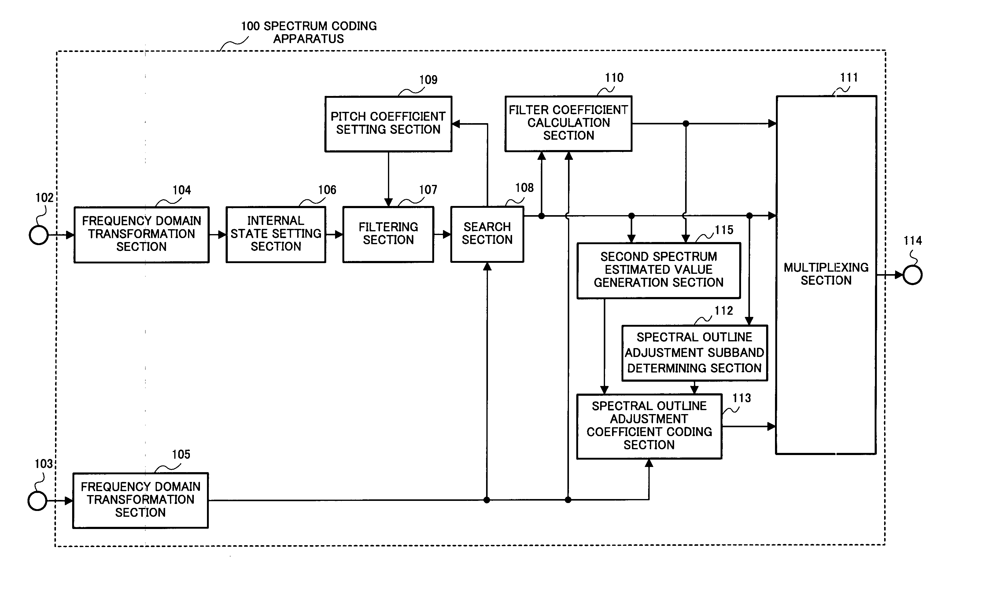
[0055]FIG. 4 is a block diagram showing the configuration of spectrum coding apparatus 100 according to Embodiment 1 of the present invention.

[0056] A first signal whose effective frequency band is 0≦k102 and a second signal whose effective frequency band is 0≦k103. Next, frequency domain transformation section 104 performs a frequency transformation on the first signal input from input terminal 102, calculates first spectrum S1(k) and frequency domain transformation section 105 performs a frequency transformation on the second signal input from input terminal 103 and calculates second spectrum S2(k) Here, discrete Fourier transform (DFT), discrete cosine transform (DCT), modified discrete cosine transform (MDCT) or the like can be applied as the frequency transformation method.

[0057] Next, internal state setting section 106 sets an internal state of a filter used in filtering section 107 using first spectrum S1(k). Filtering section 107 performs filtering based on the internal st...

embodiment 2

[0078]FIG. 9 is a block diagram showing the configuration of spectrum coding apparatus 200 according to Embodiment 2 of the present invention. Since this embodiment adopts a simple configuration for a filter used at a filtering section, it requires no filter coefficient calculation section and produces the effect that a second spectrum can be estimated with a small amount of calculation. In FIG. 9, components having the same names as those in FIG. 4 have identical functions, and therefore detailed explanations of such components will be omitted. For example, spectral outline adjustment subband determining section 112 in FIG. 4 has a name “spectral outline adjustment subband determining section” identical to the spectral outline adjustment subband determining section 209 in FIG. 9, and therefore it has an identical function.

[0079] The configuration of the filter used at filtering section 206 is a simplified one as shown in the following expression. P⁡(z)=11-z-T(12)

[0080] Expression...

embodiment 3

[0083]FIG. 11 is a block diagram showing the configuration of spectrum coding apparatus 300 according to Embodiment 3 of the present invention. The features of this embodiment include dividing a band FL-≦k

[0084] This avoids the problem with discontinuity of spectral energy caused by a spectral tilt included in the spectrum in a band of 0≦k

[0085] Subband division section 309 divides band FL≦k2(k) given f...


PUM

PropertyMeasurementUnit
frequencyaaaaaaaaaa
frequencyaaaaaaaaaa
frequencyaaaaaaaaaa

Abstract

A spectrum coding apparatus capable of performing coding at a low bit rate and with high quality is disclosed. This apparatus is provided with a section that performs the frequency transformation of a first signal and calculates a first spectrum, a section that converts the frequency of a second signal and calculates a second spectrum, a section that estimates the shape of the second spectrum in a band of FL≦k<FH using a filter having the first spectrum in a band of 0≦k<FL as an internal state and a section that codes an outline of the second spectrum determined based on a coefficient indicating the characteristic of the filter at this time.

Description

TECHNICAL FIELDS [0001] The present invention relates to a method of extending a frequency band of an audio signal or voice signal and improving sound quality, and further to a coding method and decoding method of an audio signal or voice signal applying this method. BACKGROUND ART [0002] A voice coding technique and audio coding technique which compresses a voice signal or audio signal at a low bit rate are important for the effective utilization of a transmission path capacity of radio wave or the like in a mobile communication and a recording medium. [0003] Voice coding for coding a voice signal includes schemes such as G726 and G729 standardized in the ITU-T (International Telecommunication Union Telecommunication Standardization Sector). These schemes target narrow band signals (300 Hz to 3.4 kHz) and can perform high quality coding at 8 kbits / s to 32 kbits / s. However, because such a narrow band signal has a frequency band as narrow as a maximum of 3.4 kHz, and as for quality, ...

Claims


Application Information

Patent Timeline
Patent Type & Authority Applications(United States)
IPC IPC(8): H04K1/10G01L19/02G10L19/02G10L21/0388G10L25/90
CPCG10L21/038G10L19/0204G10L19/02
Inventor OSHIKIRI, MASAHIRO
Owner PANASONIC CORP
Why Eureka
Try Eureka