Method for creating a temporary dental crown

a dental crown and temporary technology, applied in the field of dental crown or bridge procedure, can solve the problems of time-consuming and inability to obtain the proper final impression of the tooth, and achieve the effect of reducing the overall time required for the procedure and reducing the time required

Inactive Publication Date: 2007-03-29
JAGHAB JEFFREY
View PDF9 Cites 9 Cited by
  • Summary
  • Abstract
  • Description
  • Claims
  • Application Information

AI Technical Summary

Benefits of technology

[0015] This procedure eliminates the necessity for applying the astringent to the gums in on or more separate step

Problems solved by technology

A proper final impression of the tooth cannot be obtained if bleeding occurs because bleeding will cause bubbles or voids.
The need for a

Method used


Image

  • Method for creating a temporary dental crown
  • Method for creating a temporary dental crown

Examples


Embodiment Construction

)

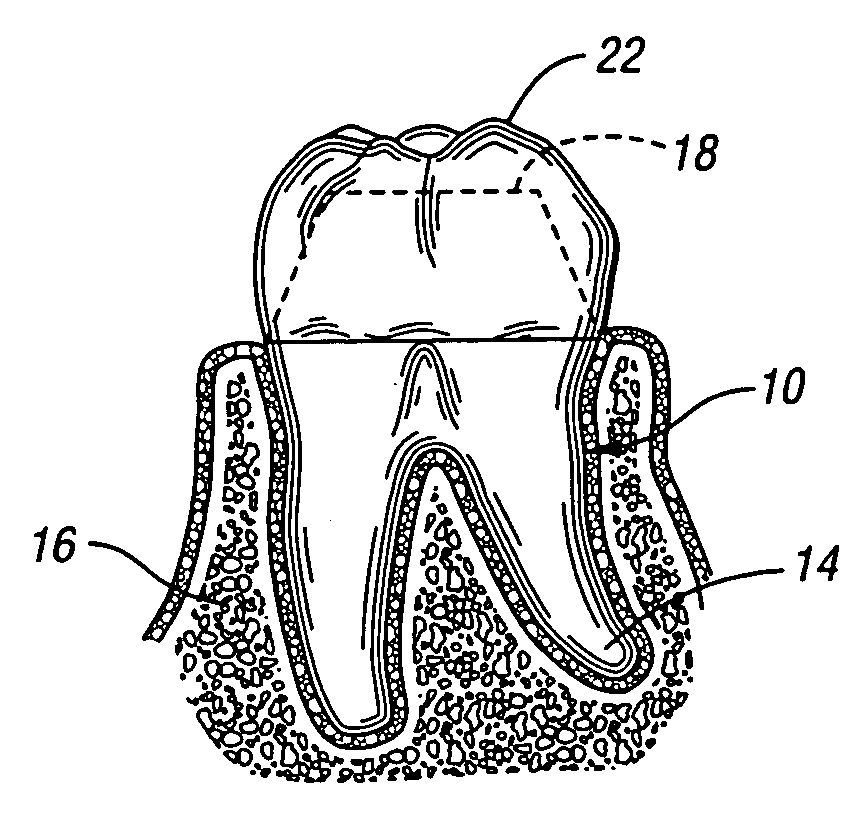
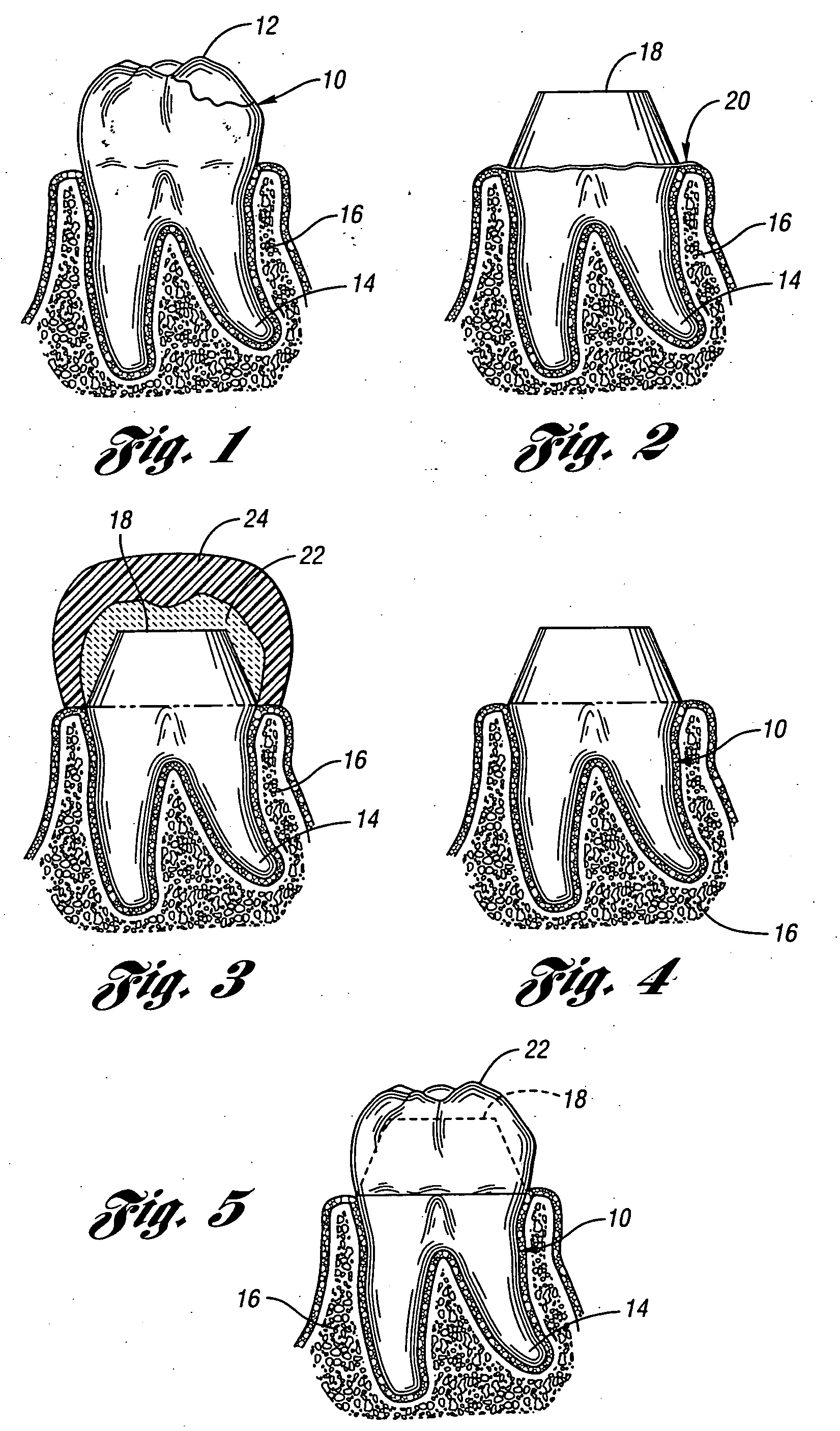
[0021]FIG. 1 shows a tooth 10 before crown preparation. It will have been determined that the tooth 10 is decayed or otherwise defective at the upper portion 12. This defective portion necessitates removing the defective portion and preparing it for the application of a permanent replacement. FIG. 1 also shows tooth roots 14 and surrounding gum tissue 16. The gum tissue 16 surrounds the entire perimeter of the tooth roots 14.

[0022] Before preparing a permanent replacement for the defective portion, a preliminary impression mold 24 of the tooth with the defective portion must be formed. The preliminary impression mold 24 is made using wax, plastic, polyvinylsiloxane or other suitable materials. The preliminary impression mold 24 is formed by placing preliminary impression material over the defective tooth 10 thereby forming an impression in the shape of the defective tooth 10.

[0023]FIG. 2 shows the tooth 10 after it has been prepared for receiving a crown. The defective portions a...


PUM


Abstract

A method for making a temporary dental crown is disclosed. The temporary crown material that is used includes an astringent, which forms part of the material itself, to control bleeding in the gums of the patient whereby the steps involved in the procedure are simplified and minimal time is required to perform the procedure.

Description

CROSS-REFERENCE TO RELATED APPLICATIONS [0001] This application claims the benefit of U.S. provisional application Ser. No. 60 / 720,644 filed Sep. 26, 2005.BACKGROUND OF THE INVENTION [0002] 1. Field of the Invention [0003] The invention relates to a procedure for making a dental crown or bridge using simplified method steps. [0004] 2. Background Art [0005] In a known procedure for creating a temporary dental crown or bridge, the gum of a patient is numbed with a local anesthetic. After the patient's gum is numbed, a preliminary impression is made of the tooth that is to receive a crown. The preliminary impression is made using wax, plastic, polyvinylsiloxane, etc. In preparing a tooth for receiving the crown, the defective regions of an otherwise healthy tooth are removed by grinding, thereby leaving a robust support pedestal that will provide a secure base for the dental crown when the dental crown is secured in place by an adhesive. [0006] After the tooth is prepared, a temporary ...

Claims


Application Information

Patent Timeline
IPC IPC(8): A61C5/00
CPCA61C13/0001A61C5/10A61C5/77
Inventor JAGHAB, JEFFREY
Owner JAGHAB JEFFREY
Why Eureka
Try Eureka