Modular dual wheel drive assembly, wheeled devices that include modular dual wheel drive assemblies and methods for moving and/or maneuvering wheeled devices using modular dual wheel drive assemblies

a technology of modular dual wheel drive and drive assembly, which is applied in the direction of electric propulsion mounting, wheelchair/patient conveyance, manufacturing tools, etc., can solve the problems of insufficient power obtained from such scaled-down large-scale drive system for small-scale self-propelled wheels, limited steering range, and limited power supply

Active Publication Date: 2007-04-12
CYCOGS
View PDF12 Cites 105 Cited by
  • Summary
  • Abstract
  • Description
  • Claims
  • Application Information

AI Technical Summary

Benefits of technology

[0016] This invention separately provides a self-propelled wheel assembly for a self-propelled machine having improved load weight distribution,
[0030] In various exemplary embodiments, the relative position between the mounting plate and the frame can be adjusted by appropriately energizing the height adjusting motor. Depending on the direction the height adjusting motor is driven, the vertical lift screw is rotated relative to the vertical lift nut to move the frame closer to or farther away from the mounting plate. Because the mounting plate is attached to the machine, device or load that is supported by the wheel assembly, and the wheels on the support surface support the frame, this alters the distance between the machine, device or load and the wheels. If this distance is reduced, and the machine, device or load that is otherwise fully supported, such as by the other wheel assemblies, this will cause the wheels to be lifted from the support surface Otherwise, this will cause the machine, device or load that is supported by the wheel assembly to dip or tilt toward the support surface. If this distance is increased, and the machine, device or load is supported by this wheel assembly, the machine, device or load will be lifted or tilted away from the support surface. Otherwise, the wheels will be lowered toward the support surface.

Problems solved by technology

These large-scale machines are typically used to move extremely heavy and / or large loads, and thus typically have extremely large or oversized wheels and / or tires that are typically in the six to twelve foot diameter range.
Typically, such large-scale self-propelled wheels provided only limited steering ranges, although some of the more complicated designs, such as that shown in the '030 patent, will allow for 360° rotation of the wheels.
However, due to the complicated nature of such drive systems, it is effectively impossible to scale such drive systems down for use with small-scale self-propelled wheels.
Additionally, because the power / weight ratios of such large-scale drive systems do not adequately scale down, even if it were possible to provide a scaled-down version of the drive system, the amount of power that could be obtained from such scaled-down large-scale drive systems would be inadequate for small-scale wheels.
This simple design has significant limitations, such as poor or imprecise position, velocity and / or acceleration control, and the inability to move freely in any direction.
Such small-scale machines are also subject to rocking about the caster wheels, which typically results in loss of traction and vehicle sway.
Because such small-scale self-propelled machines typically support significant loads relative to the size of the contact area, rotating the wheels about the steering axis / pivot point typically causes the wheels to slide, rather than roll on the support surface, such as a floor, thus scuffing the support surface.
Scuffing not only can leave marks or other discolorations on the support surface, but can actively damage the support surface if the sliding friction of the wheel is sufficiently high.
However, locked gearing also prevents many precision movements.
Since the wheels cannot move independently, such synchro-drive machines cannot pivot, spin on their axis, or perform a simulated skid as a maneuver.
Additionally, large volumes of space are taken up by the centralized motors, gears, belts, chains, shafts and other mechanical devices used to transmit power from the central motors synchronously to the driven wheel assemblies.
In either case, the weight distribution of the supported load on each wheel assembly is an issue, as all the weight for each wheel is concentrated onto the small surface area contact patch of the wheel.
Again, rotation around the steering axis, whether in synchro-drive machines or holonomic machines, typically causes scuffing and floor damage.

Method used


Image

  • Modular dual wheel drive assembly, wheeled devices that include modular dual wheel drive assemblies and methods for moving and/or maneuvering wheeled devices using modular dual wheel drive assemblies
  • Modular dual wheel drive assembly, wheeled devices that include modular dual wheel drive assemblies and methods for moving and/or maneuvering wheeled devices using modular dual wheel drive assemblies
  • Modular dual wheel drive assembly, wheeled devices that include modular dual wheel drive assemblies and methods for moving and/or maneuvering wheeled devices using modular dual wheel drive assemblies

Examples


Embodiment Construction

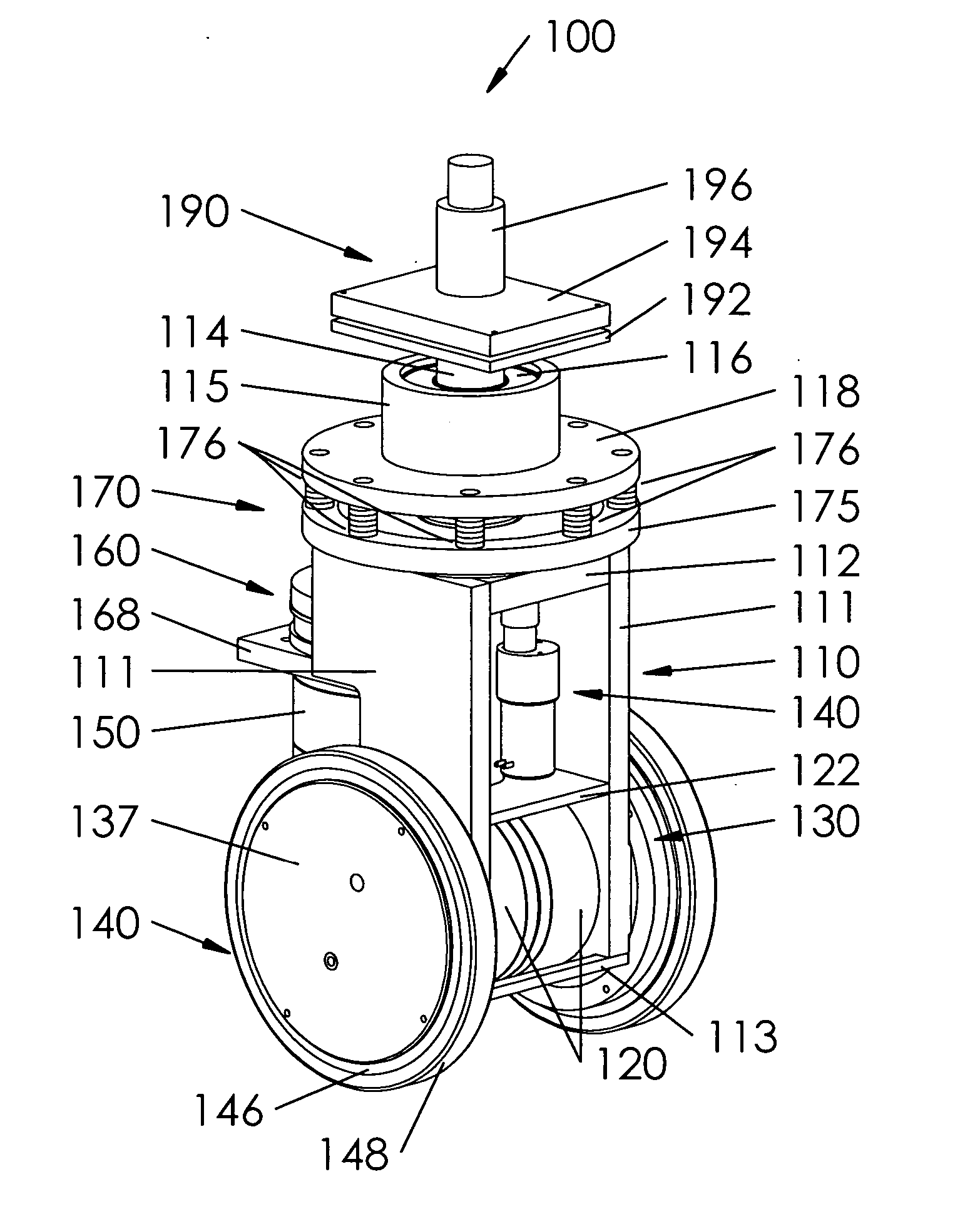
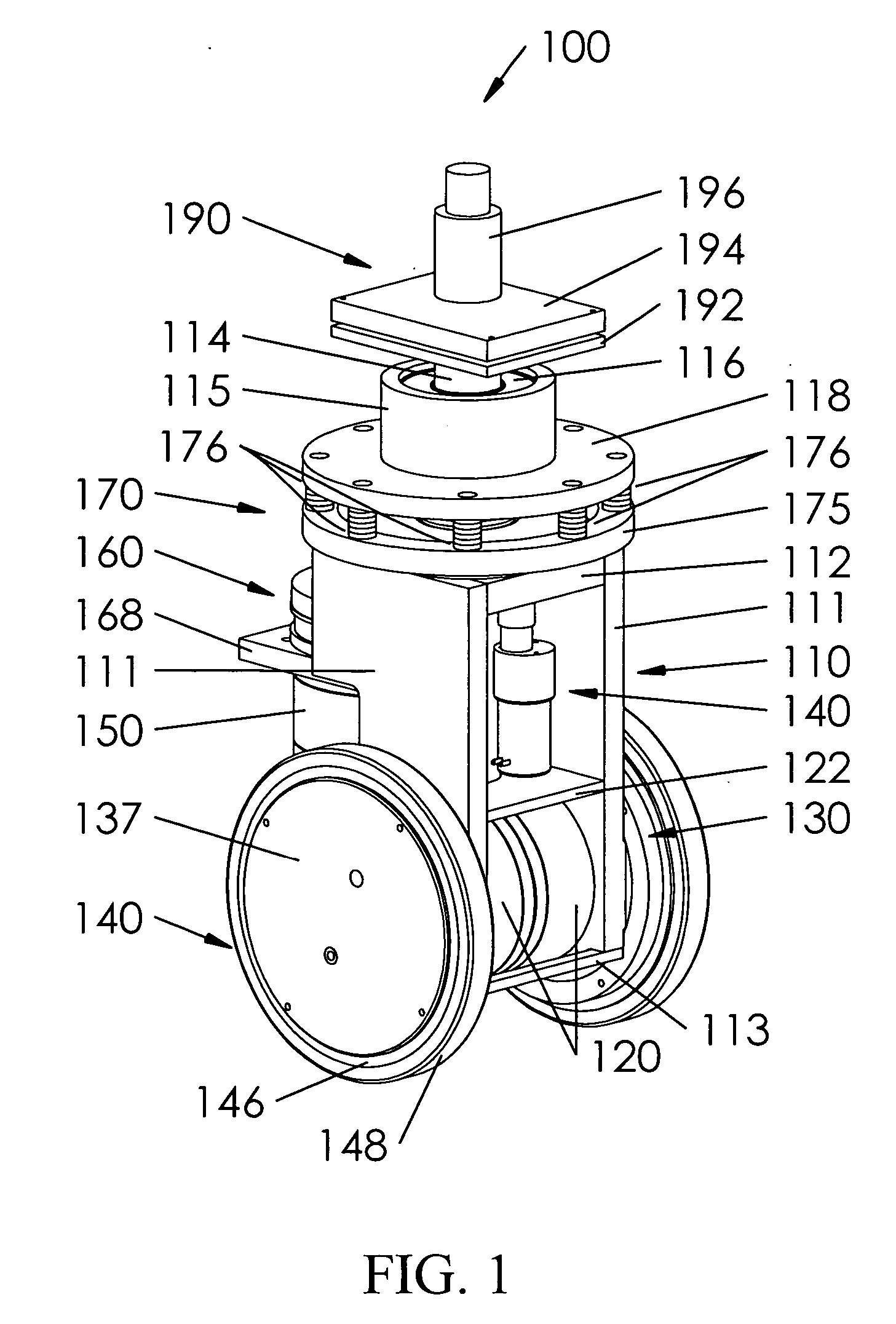
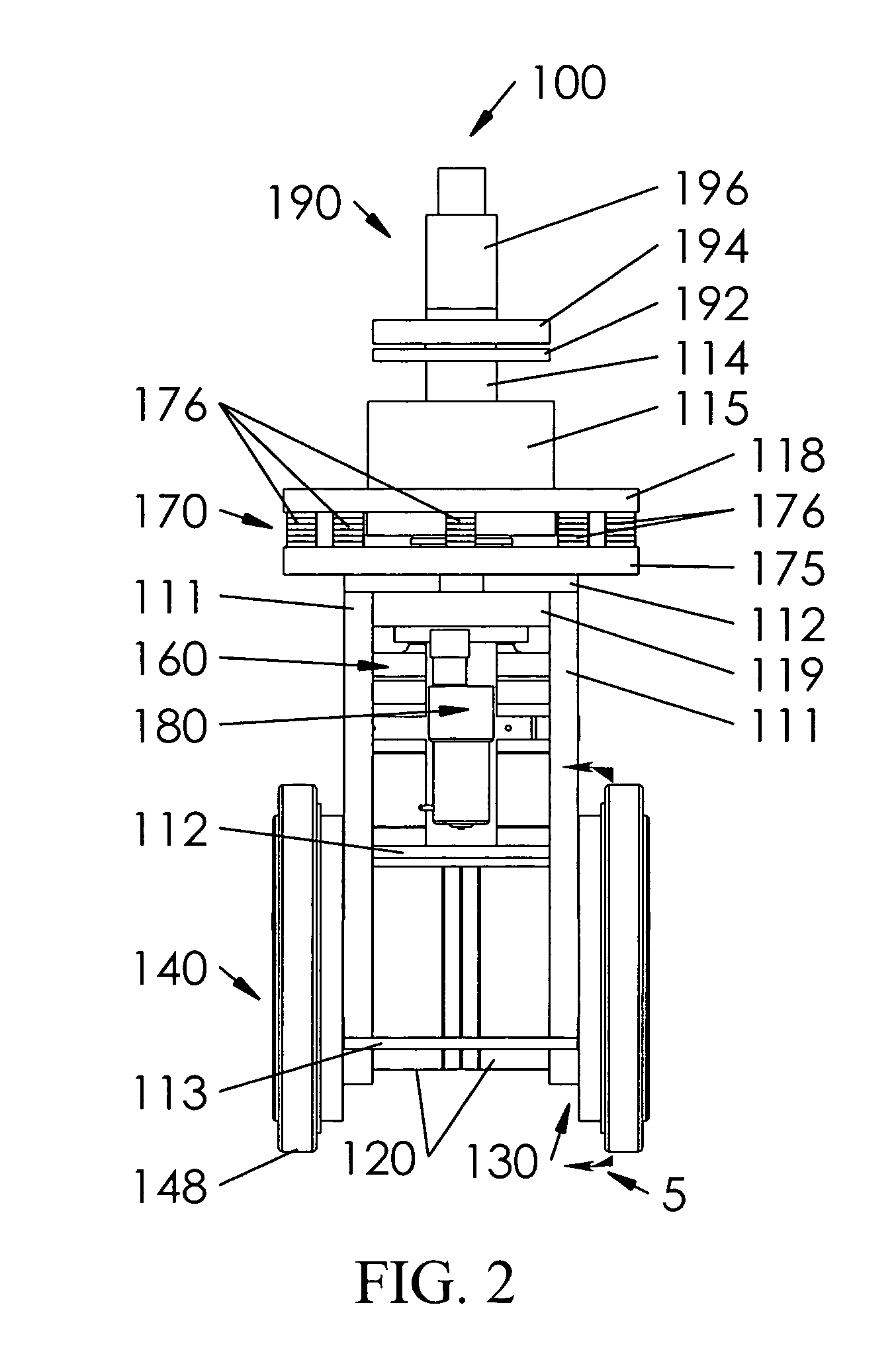
[0013] Typical large-scale self-propelled vehicles provide at least one drive motor for each wheel assembly. However, due to the size of the wheel assemblies, the types of drive motors used with such large-scale machines are inappropriate for use with small-scale machines. The drive systems conventionally used with small-scale self-propelled machines do not provide sufficient mobility or maneuverability for the small-scale self-propelled machines, do not provide sufficient degrees of freedom and / or are unable to avoid scuffing and / or otherwise avoiding damage to the surface on which the small-scale self-propelled machine moves.

[0014] This invention provides a dual-wheel self-propelled wheel assembly.

[0015] This invention further provides dual-wheel self-propelled wheel assemblies for self-propelled machines.

[0016] This invention separately provides a self-propelled wheel assembly for a self-propelled machine having improved load weight distribution,

[0017] This invention separate...


PUM


Abstract

A wheel assembly for a small-scale machine includes a pair of opposing, individually-driven wheels, associated motors and possibly one or more gear assemblies. The motors receive separate drive signals from a control electronics subsystem of the wheel assembly. The motors can be connected to the wheels via the gear assemblies. Because the wheels are separately driven, driving the two wheel assemblies at similar or different speeds drives the wheel assembly over straight or curved paths. An orientation assembly allows the orientation of the wheels to the machine to be controllably altered. A height adjusting assembly allows the distance between the wheels and a point on the machine where the wheel assembly is attached to be adjusted. The rotational axis that the wheel assembly rotates about when re-oriented need not pass through either wheel of the wheel assembly. The wheels can be driven by control signals generated by on-board control electronics.

Description

BACKGROUND OF THE INVENTION [0001] 1. Field of the Invention [0002] This invention is directed to drive assemblies for self-propelled wheeled devices. [0003] 2. Related Art [0004] Devices or machines having self-propelled wheels typically occupy two distinct points along the size spectrum. At one end of the side spectrum lie the “mega machines” or “monster machines”, as they are commonly referred to in the media. These large-scale machines are typically used to move extremely heavy and / or large loads, and thus typically have extremely large or oversized wheels and / or tires that are typically in the six to twelve foot diameter range. Such large-scale machines are disclosed in, for example, U.S. Pat. Nos. 3,197,229; 3,280,931; 3,645,406; 4,003,447; 4,599,030; 5,165,838; 5,618,151 and U.S. Pat. No. 6,328,123 and published U.S. patent application Ser. No. 2002 / 0175009. [0005] Because the wheels for such large-scale machines are so large, it is possible to place electromotive, hydraulic,...

Claims


Application Information

Patent Timeline
Patent Type & Authority Applications(United States)
IPC IPC(8): B62D61/00
CPCA61G5/045A61G2203/14B25J5/007B60B11/06B60B19/00B60B27/0021B60B27/0047B60B2200/26B60B2200/43B60Y2200/60B62B5/004B62B2301/00B62D5/0418B62D7/04A61G2203/42
Inventor TOBEY, WAYLAND E.DAVIS, PETER D.
Owner CYCOGS
Why Eureka
Try Eureka