Umbrella frame

Inactive Publication Date: 2007-04-19
LI MING GUNG
View PDF19 Cites 2 Cited by
  • Summary
  • Abstract
  • Description
  • Claims
  • Application Information

AI Technical Summary

Benefits of technology

[0009] A main objective of the present invention is to provide an umbrella frame that has pin heads individually formed on branches and support ribs and has multiple corresponding retaining slots defined in a upper base and a l

Problems solved by technology

However, combination the runner 5 and the multiple stretchers 4 is achieved

Method used


Image

  • Umbrella frame
  • Umbrella frame
  • Umbrella frame

Examples


Example

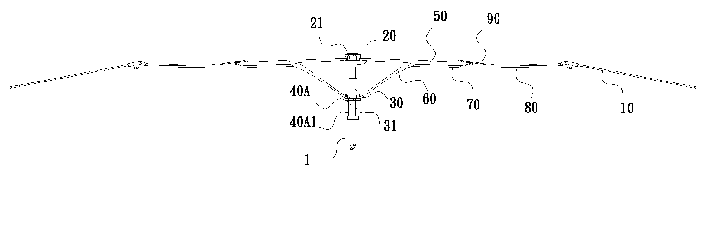
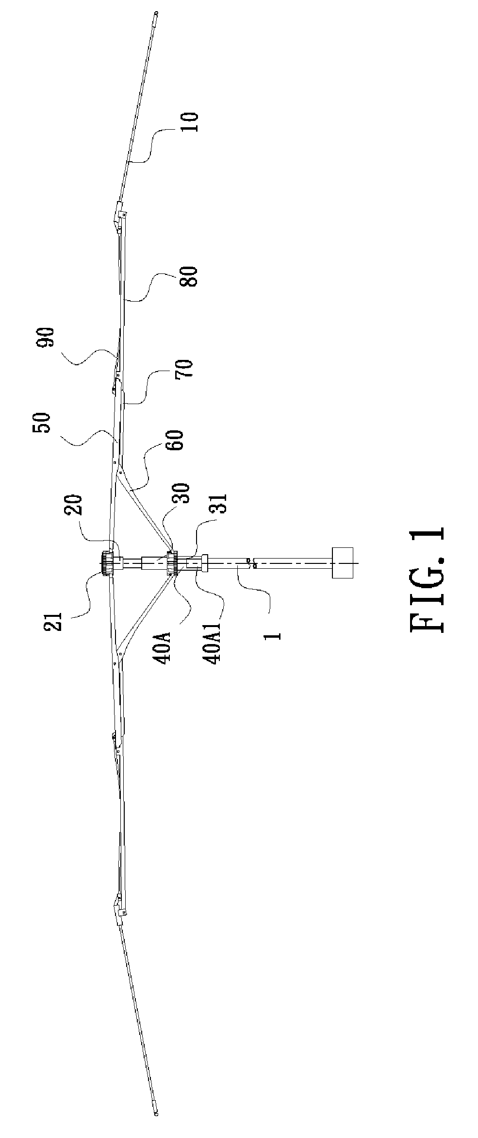
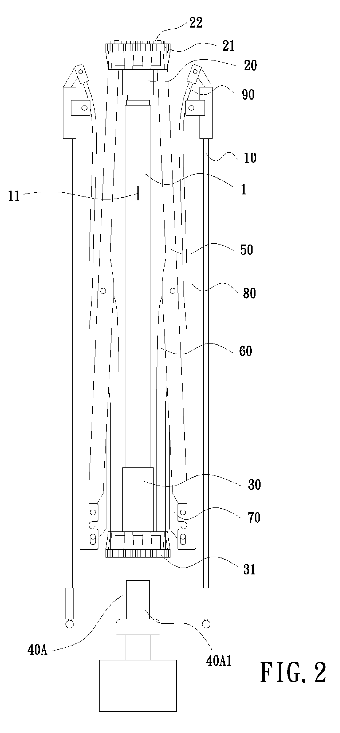
[0040] An umbrella frame in accordance with the present invention is preferably made of high-stiffness plastic and comprises a main shaft and multiple branches pivotally attached around the main shaft. The main shaft has an upper base and a lower base each having multiple retaining slots. Each branch is divided into a front section, a middle section and a rear section and has a supporting rib and a pulling rib both pivotally attached under the front section. The front sections and the supporting ribs have pin heads to respectively engage the retaining slots on the upper and lower bases so that the branches are pivotally attached to the main shaft. Moreover, the supporting rib, the pulling ribs, the front section and middle section perform a quaternary-linkage to make operation conveniently and stably. Additionally, the umbrella frame is made of high-stiffness plastic material so that stiffness is also improved.

[0041] With reference to FIGS. 1 and 2, the umbrella frame comprises a m...


PUM


Abstract

An umbrella frame has a main shaft and multiple branches pivotally attached around the main shaft. The main shaft has an immovable upper base and a movable lower base each having multiple retaining slots. Each branch is divided into a front section, a middle section and a rear section and has a supporting rib and a pulling rib both pivotally attached under the front section. Improvement of the umbrella frame is that the upper and lower bases respectively have multiple rectangular recesses individually and pivotally engaged pin heads on the front section or the supporting rib of each branch. Thereby, the umbrella frame is be quickly assembled or disassembled.

Description

[0001] This is a continuation-in-part (CIP) of U.S. patent application Ser. No. 11 / 162,314, filed on Sep. 6, 2005, which is incorporated herein by reference.BACKGROUND OF THE INVENTION [0002] 1. Field of the Invention [0003] The present invention relates to an umbrella frame, and more particularly to an umbrella frame that is convenient in assembly or disassembly. [0004] 2. Description of Related Art [0005] With reference to FIGS. 12 and 13, a conventional umbrella frame is composed of a umbrella shaft 1, a retainer 2 mounted at a top of the umbrella shaft, multiple ribs 3 radially attached to the retainer 2, and multiple stretchers 4 corresponding attached to the multiple ribs 3 and a runner mounted on the umbrella shaft 1 to collect all inner ends of the stretchers 4. The retainer 2 mounted on the top of the umbrella shaft 11 equally attaché inner ends of the ribs 3 with same intervals. Moreover, each stretcher 4 is attached to a middle of a corresponding rib 3. The runner 5 also ...

Claims


Application Information

Patent Timeline
IPC IPC(8): A45B25/06
CPCA45B19/10A45B25/02
Inventor LI, MING-GUNG
Owner LI MING GUNG
Why Eureka
Try Eureka