Liquid crystal display device and method of fabricating the same

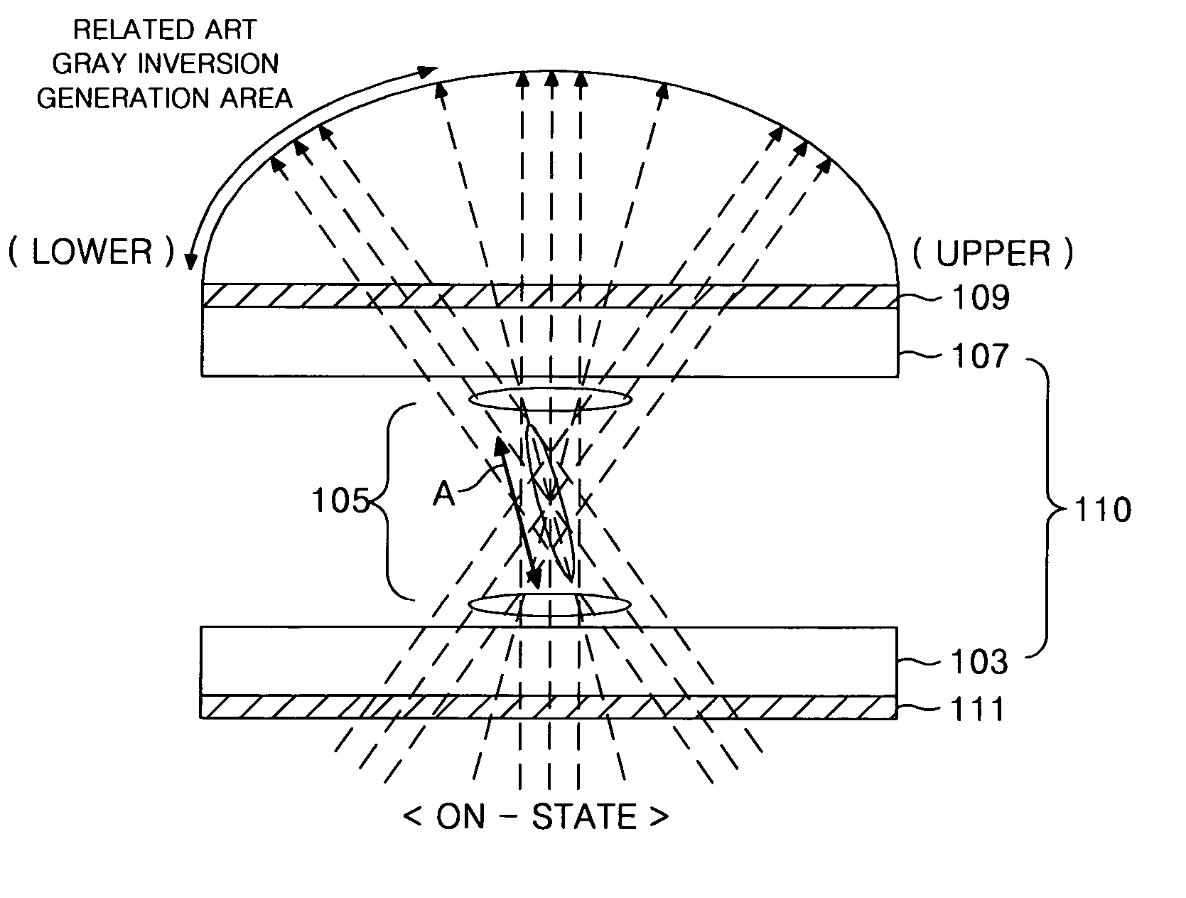
a technology of liquid crystal display and liquid crystal, which is applied in non-linear optics, instruments, optics, etc., can solve the problem that the vertical electric field type lcd can suffer from a gray inversion phenomenon

Active Publication Date: 2007-04-19
LG DISPLAY CO LTD
View PDF12 Cites 3 Cited by
  • Summary
  • Abstract
  • Description
  • Claims
  • Application Information

AI Technical Summary

Benefits of technology

[0021] To achieve these and other advantages and in accordance with the purpose of the present invention, as embodied and broadly described herein, a liquid crystal display device includes a liquid crystal display panel; a first polarizer on a first surface of the liquid crystal display panel; a second polarizer on a second surface of the liquid crystal display panel; and a first light path control film on a first surface of the second polarizer to refract the light polarized by the second polarizer to a direction minimizing a gray inversion on a display surface of the liquid crystal display panel.
[0022] In another aspect, a liquid crystal display device includes a liquid crystal display panel; a first polarizer on a first surface of the liquid crystal display panel to polarize a light incident to the liquid crystal display panel; a second polarizer on a second surface of the liquid crystal display panel to polarize the light transmitted through the liquid crystal display panel; a first light path control film on a first surface of the first polarizer to refract the light incident onto the first polarizer; and a second light path control film on a first surface of the second polarizer to refract the light polarized by the second polarizer to a direction minimizing a gray inversion on a display surface of the liquid crystal display panel.
[0023] In another aspect, a liquid crystal display device includes a liquid crystal display panel including a liquid crystal tilted at a direction corresponding to an average director of the liquid crystal; a polarizer located in an exit surface of the liquid crystal display panel to polarize the light transmitted through the liquid crystal display panel; and a first light path control film located on a first surface of the polarizer to refract the polarized light toward a direction minimizing a gray inversion on a display surface of the liquid crystal display panel at an angle smaller than an angle of the average director.
[0024] In another aspect, a method of fabricating a liquid crystal display device including a liquid crystal panel and a liquid crystal in the liquid crystal panel includes tilting a liquid crystal at a direction corresponding to an average director; polarizing a light transmitted through the liquid crystal display panel at an exit surface of the liquid crystal display panel; and refracting the polarized light toward a direction minimizing a gray inversion on a display surface of the liquid crystal display panel at an angle lower than an angle of the average director.

Problems solved by technology

However, the vertical electric field type LCD typically provides a narrow viewing angle.
Moreover, the vertical electric field type LCD can suffer from a gray inversion phenomenon appearing at a lower viewing angle, for example, at lower part of the liquid crystal display panel.

Method used


Image

  • Liquid crystal display device and method of fabricating the same
  • Liquid crystal display device and method of fabricating the same
  • Liquid crystal display device and method of fabricating the same

Examples


first embodiment

[0049]FIG. 7 is a schematic view of an exemplary liquid crystal display device according to the present invention. Referring to FIG. 7, a liquid crystal display device includes a TN mode LCD panel 110 having an upper substrate 107 and a lower substrate 103 with a liquid crystal layer 105 between the lower and upper substrates 103 and 107. An upper polarizer 109 is adhered to a light exit surface of the upper substrate 107, and a lower polarizer 111 is adhered to a light incidence surface of the lower substrate 103. The upper polarizer 109 can be an analyzer. The upper polarizer 109 has a light transmission axis in a first direction. The lower polarizer 111 has a light transmission axis perpendicularly to the light transmission axis of the upper polarizer 109.

[0050] A light path control film 120 is formed on the outer surface of the upper polarizer 109. The light path control film 120 can be, for example, an optical layer. The light path control filn 120 controls the light transmitte...

second embodiment

[0061]FIG. 10 is a schematic view of an exemplary liquid crystal display device according to the present invention. Referring to FIG. 10, a liquid crystal display device includes a TN mode LCD panel 110 having an upper substrate 107 and a lower substrate 103 with a liquid crystal layer 105 between the lower and upper substrates 103 and 107. An upper polarizer 109 is adhered to a light exit surface of the upper substrate 107, and a lower polarizer 111 is adhered to a light incidence surface of the lower substrate 103.

[0062] A light path control film 120 is formed on the outer surface of the upper polarizer 109. The light path control film 120 controls the light transmitted through the liquid crystal display panel 110. For example, the light path control film 120 refracts light in a fixed angle.

[0063] A light dispersion processing layer 130 is provided on the light path control film 120. The light dispersion processing layer 130 distributes and disperses the light refracted by the li...

third embodiment

[0070]FIG. 12A is a schematic view of an exemplary liquid crystal display device according to the present invention. Referring to FIG. 12A, a liquid crystal display device includes a TN mode LCD panel 110 having an upper substrate 107 and a lower substrate 103 with a liquid crystal layer 105 between the lower and upper substrates 103 and 107. An upper polarizer 109 is adhered to a light exit surface of the upper substrate 107, and a lower polarizer 111 is adhered to a light incidence surface of the lower substrate 103.

[0071] A first light path control film 120 is formed on the outer surface of the upper polarizer 109. A second light path control film 122 is formed on the outer surface of the lower polarizer 111. The first light path control film 120 controls the light transmitted through the liquid crystal display panel 110. The second light path control film 122 controls the light incident onto the lower polarizer 111. For example, the second light path control film 122 refracts th...


PUM

PropertyMeasurementUnit
refractive indexaaaaaaaaaa

Abstract

A liquid crystal display device includes a liquid crystal display panel; a first polarizer on a first surface of the liquid crystal display panel; a second polarizer on a second surface of the liquid crystal display panel; and a first light path control film on a first surface of the second polarizer to refract the light polarized by the second polarizer to a direction minimizing a gray inversion on a display surface of the liquid crystal display panel.

Description

[0001] This application claims the benefit of the Korean Patent Application No. 2005-0096589 filed in Korea on Oct. 13, 2005, which is hereby incorporated by reference in its entirety. BACKGROUND OF THE INVENTION [0002] 1. Field of the Invention [0003] The present invention relates to a liquid crystal display device, and more particularly to a liquid crystal display device and a method of fabricating the same that reduces a gray inversion phenomenon. [0004] 2. Description of the Related Art [0005] A liquid crystal display LCD device displays a picture by controlling an electric field applied to a liquid crystal cell to modulate the light incident to the liquid crystal cell. Depending on the direction of the applied electric field driving the liquid crystal, a liquid crystal display device is broadly classified as a vertically applied electric field type or a horizontally applied electric field type. [0006] In the vertically applied electric field type of LCD device, a pixel electrod...

Claims


Application Information

Patent Timeline
Patent Type & Authority Applications(United States)
IPC IPC(8): G02F1/1335
CPCG02F1/133504G02F1/133526G02F2001/133562G02F2203/30G02F1/133562G02F1/1335
Inventor PARK, CHI HYUCK
Owner LG DISPLAY CO LTD
Why Eureka
Try Eureka