Optical device

a technology of optical devices and housings, applied in the field of optical devices, can solve problems such as foreign matter entering the housing, situations may occur, and achieve the effect of swiftly restoring a function as an optical device with stability

Inactive Publication Date: 2007-04-19
HOKUYO AUTOMATIC CO
View PDF9 Cites 10 Cited by
  • Summary
  • Abstract
  • Description
  • Claims
  • Application Information

AI Technical Summary

Benefits of technology

[0022] With this construction, when the optical window formed separately from the housing is spliced to the housing through bonding or the like, by forming the electric contact points at the splicing surfaces of the housing and the optical window and detecting an electric change of the electric contact points concurrently with or separately from the housing breakage detection, it becomes possible to detect a change of the splicing states of the housing and the optical window. That is, it becomes possible to detect a situation in which a part of the optical window peels off the housing, or the like at an early stage and with reliability by detecting an electric change of the electric contact points formed at the splicing surfaces of the housing and the optical window.
[0023] According to the present invention described above, when the housing is broken in the region in which the electrically conducting region is provided, an electric change occurs in the electrically conducting region due to the breakage of the housing. Therefore, by measuring this electric change, it becomes possible to detect the breakage of the housing at an early stage and with reliability. In addition, the breakage of the housing is detected at an early stage, so it is sufficient to replace only the broken housing, that is, it becomes possible to use continuously the optical system accommodated in the broken housing as it is. As a result, the present invention is advantageous also in terms of economy and makes it possible to swiftly restore a function as an optical device with stability.

Problems solved by technology

Therefore, the housing sometime causes the damages when a mechanical shock is applied to the housing including the optical window.
In this type of optical devices, when a housing that accommodates an optical system is broken, a situation may occur in which foreign matter, such as a fragment of the broken housing or dust outside the housing, enters into the housing through a broken portion of the housing.
In such a situation, when no countermeasure is taken, there occurs a problem in that the optical system in the housing becomes abnormal due to the foreign matter entering into the housing and it becomes impossible to maintain a function of the optical device with stability.
With this method, however, there occurs a situation in which even when a housing is broken, the breakage is overlooked, or a situation in which the breakage of the housing is found after an unreasonably long time has passed from occurrence of the breakage of the housing, which means that the method is insufficient to cope with the problem described above.

Method used


Image

  • Optical device
  • Optical device
  • Optical device

Examples


Embodiment Construction

[0027] An embodiment of the present invention will be described below with reference to the accompanying drawings.

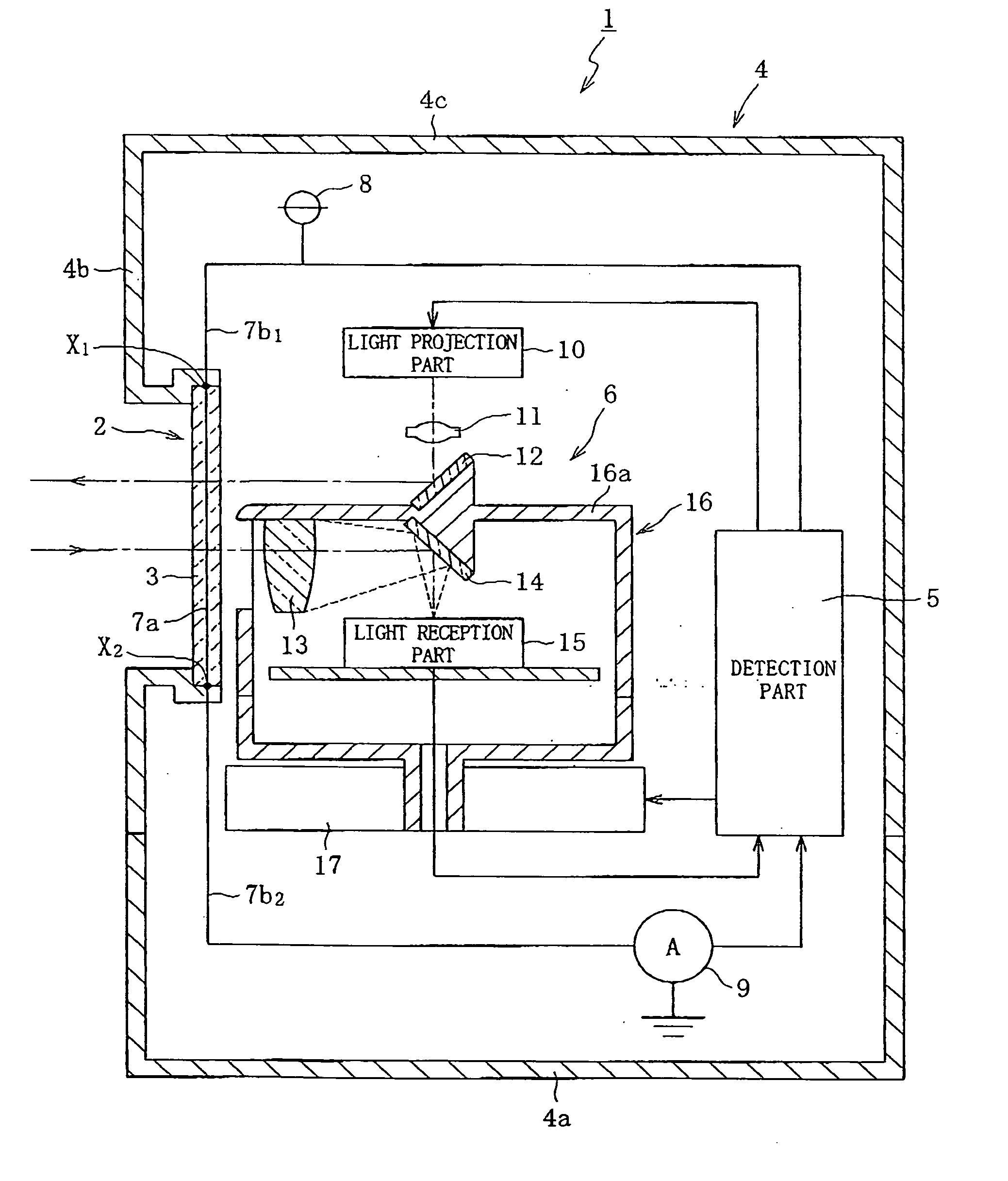
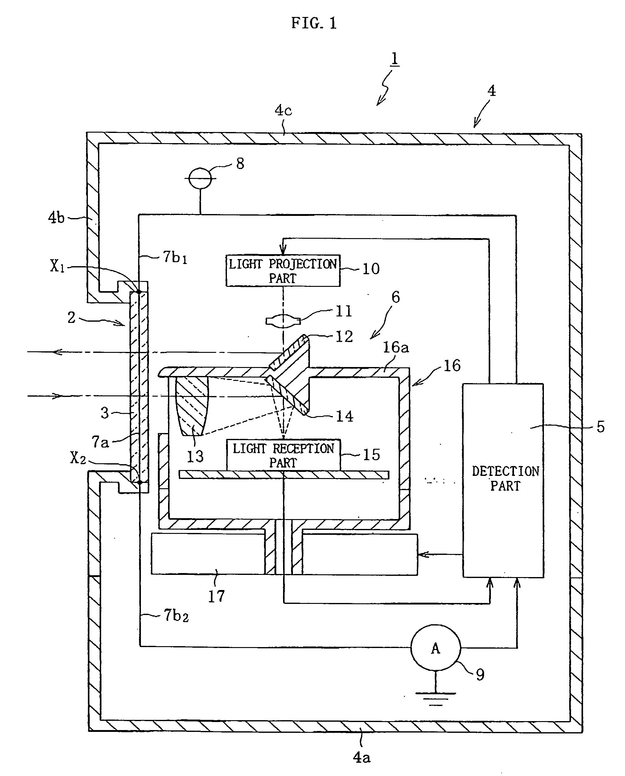
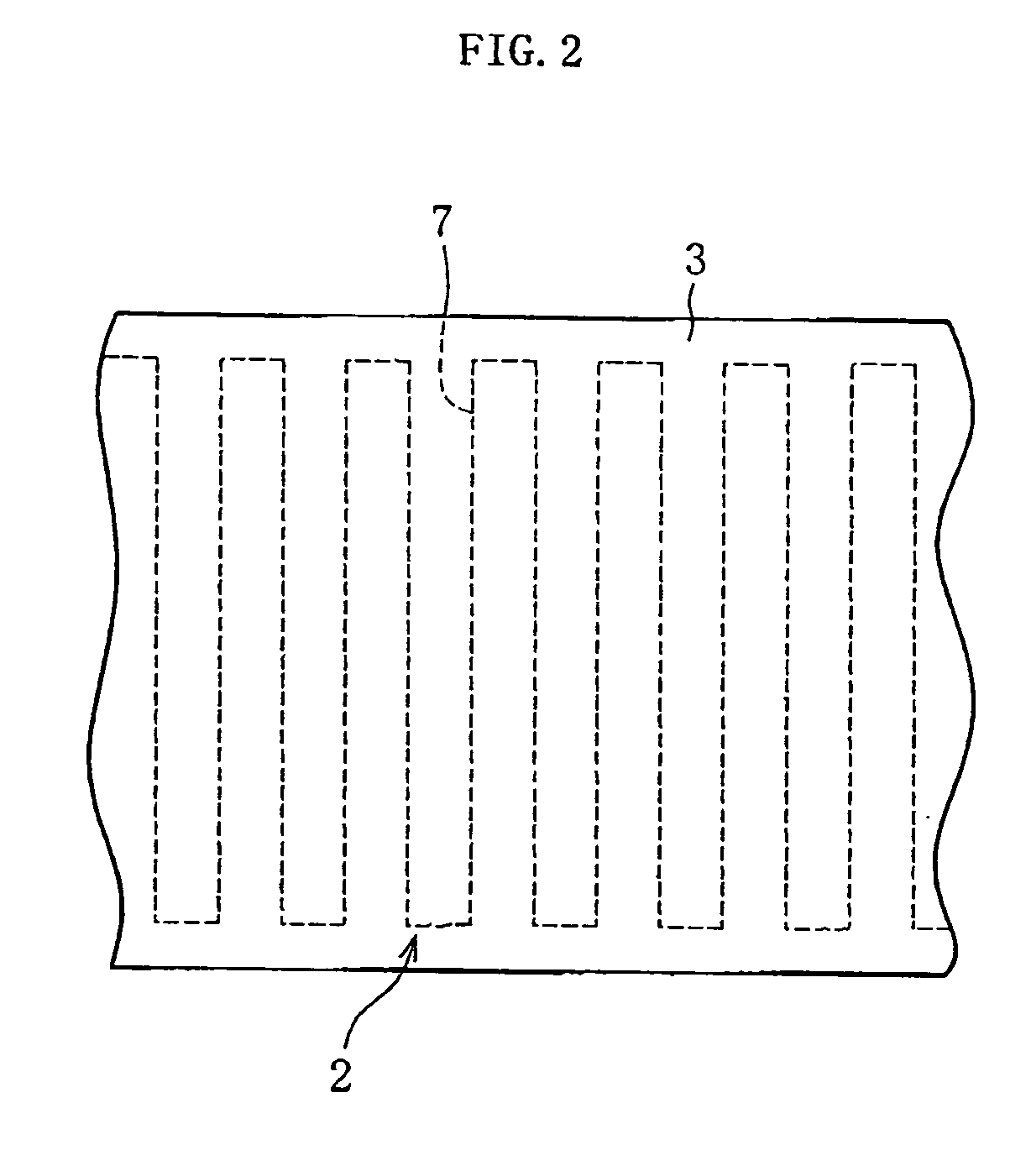
[0028]FIG. 1 is a schematic vertical cross-sectional view showing an overall construction of an optical device according to the embodiment of the present invention. As shown in FIG. 1, an optical device 1 has a construction in which in a housing 4 having an optical window 3 provided with an electrically conducting region 2, a detection part 5 that detects a breakage of the optical window 3 based on an electric change of the electrically conducting region 2 and an optical system 6 for projecting / receiving light through the optical window 3 are accommodated.

[0029] The housing 4 includes a bottom board 4a, an approximately cylindrical-shaped body portion 4b provided upright around the perimeter of the bottom board 4a, and a top board 4c for closing an upper-end opening of the body portion 4b. The optical window 3 having a horizontally annular shape and a constant width in...


PUM


Abstract

Provided is an optical device capable of detecting a breakage of a housing that accommodates an optical system at an early stage and with reliability. The optical device includes a housing having an optical window which is optically transparent and an optical system that is accommodated in the housing and projects/receives light through the optical window, and has a construction in which a electrically conducting region is provided to the optical window of the housing and a breakage of the optical window is detected based on an electric change of the current-carrying region.

Description

BACKGROUND OF THE INVENTION [0001] 1. Field of the invention [0002] The present invention relates to optical devices in which an optical system for projecting light, receiving light, or projecting / receiving light is accommodated in a light transmittable housing. [0003] 2. Description of the Related Art [0004] As is well known, optical devices having a construction in which an optical system for projecting light, receiving light, or projecting / receiving light is accommodated in a light transmittable housing, are widely used as sensors which are mounted on automated guided vehicles (AGVs) and detect obstacles or the like existing in traveling region of the AGVs, a surveillance camera installed outdoors, or the like. [0005] An example of this type of optical devices is disclosed in JP 2005-55226 A. The optical device includes a housing having an optical window. Provided within the housing are a light projection optical system for projecting light from the inside of the housing to the o...

Claims


Application Information

Patent Timeline
Patent Type & Authority Applications(United States)
IPC IPC(8): G02B23/24
CPCG08B13/04G08B13/126
Inventor MORI, TOSHIHIROTSUKUDA, SHINICHIHIGASHI, TOSHIYA
Owner HOKUYO AUTOMATIC CO
Why Eureka
Try Eureka