Alarm system with analog devices

Inactive Publication Date: 2007-04-26
TRACER ELECTRONICS
View PDF11 Cites 0 Cited by
  • Summary
  • Abstract
  • Description
  • Claims
  • Application Information

AI Technical Summary

Benefits of technology

[0007] It is an object of the present invention to provide new and

Problems solved by technology

One drawback with such an alarm system is that it is limited to switches or other digital devices and does not provide for analog input.

Method used


Image

  • Alarm system with analog devices
  • Alarm system with analog devices
  • Alarm system with analog devices

Examples


Embodiment Construction

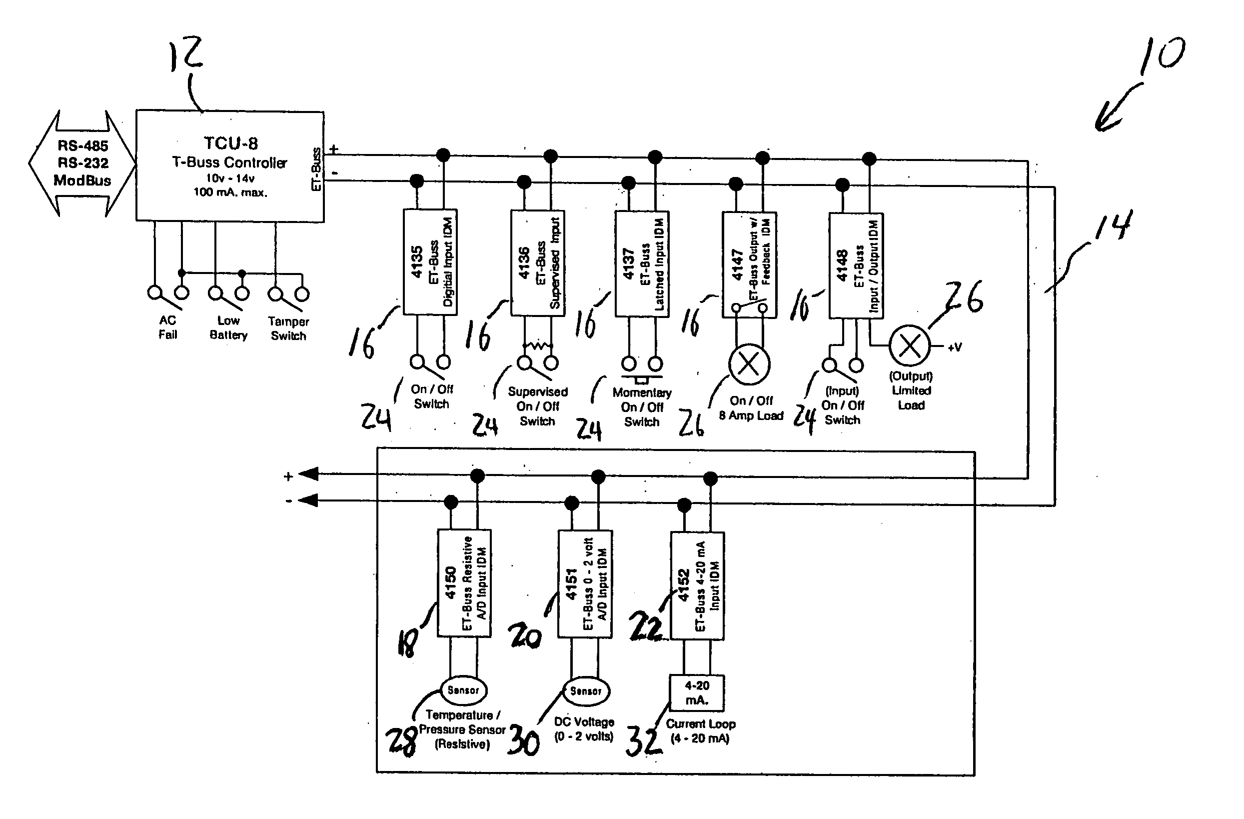
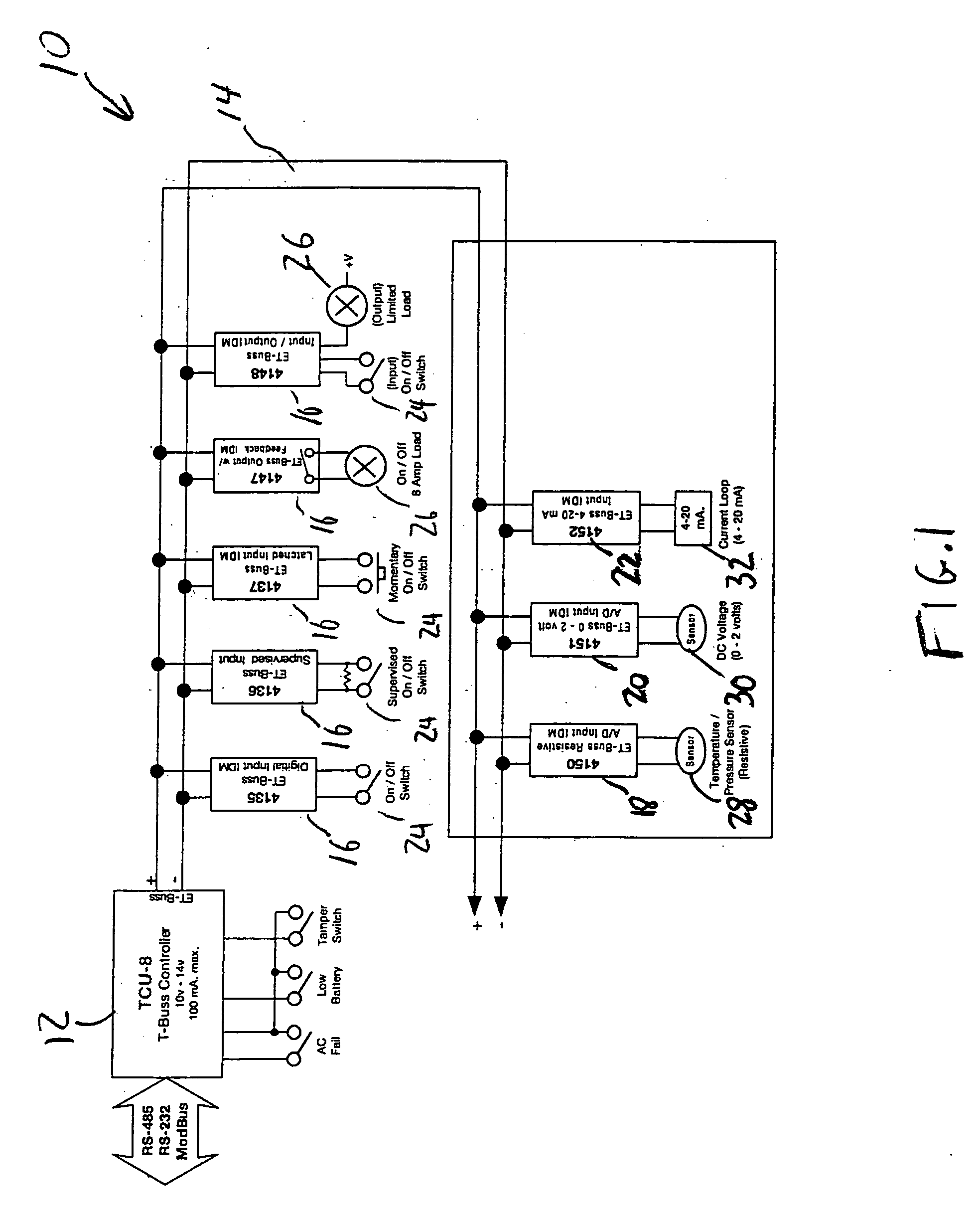
[0024] Referring the accompanying drawings wherein like reference numerals refer to the same or similar elements, an alarm system in accordance with the invention is designated 10 in FIG. 1 and comprises a controller 12, a single-wire loop 14 (which is essentially a pair of wires, one for data and the other for power), a plurality of identification modules 16, 18, 20, 22 (also referred to as IDMs herein) and various attachments to or incorporated structures on or in the identification modules 16, 18, 20, 22. The single-wire loop 14 passes through the area being monitored by the alarm system. Some attachments or incorporated structures include on / off switches 24, e.g., digital switches, and loads 26 which are used in a similar manner as the prior art single-wire loop alarm system shown in FIG. 5.

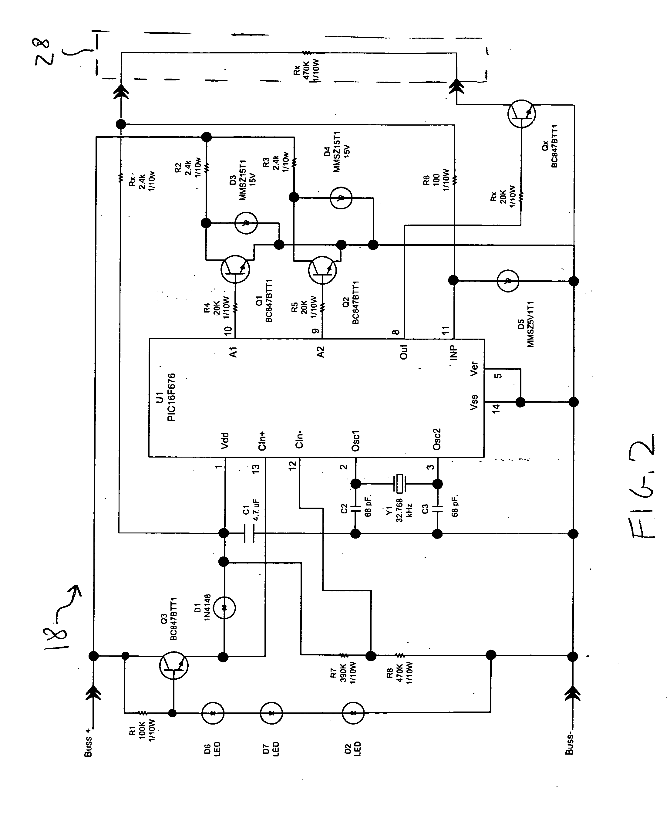
[0025] In contrast to the alarm system shown in FIG. 5 however, the alarm system 10 in accordance with the invention includes identification module 18 which is associated or integrated with ...


PUM


Abstract

Alarm system includes a controller, a single-wire loop connected to the controller, identification modules connected to the single-wire loop and attachments to or incorporated structures on or in the identification modules. Attachments or incorporated structures include digital and analog devices. Each identification module is programmed to provide a signal or report to the controller indicative of whether the associated device is in a normal state or in an alarm / trouble state. When analog devices are used, the identification modules may be designed not only to convert the analog readings to digital form but also to provide for a permitted range of variation in the sensor readings so that not all variations from a single, predetermined value of the condition being monitored by the sensor are considered indicative of a problem with the area being monitored by the sensor or a fault with the sensor.

Description

CROSS-REFERENCE TO RELATED APPLICATION [0001] This application claims priority of U.S. provisional patent application Ser. No. 60 / 729,592 filed Oct. 24, 2005, incorporated by reference herein.FIELD OF THE INVENTION [0002] The present invention relates to alarm systems, and more particularly to alarm systems including identification modules which enable analog-type measurements. [0003] The present invention also relates to single-wire loop alarm systems which enable use of both digital devices such as switches to detect conditions which trigger the alarm as well as analog sensors which can also detect other types of conditions which trigger the alarm. BACKGROUND OF THE INVENTION [0004] Alarm systems are known which include a number of switches each connected to an identification module and through common wires to a controller. The controller is capable of determining which switches are tripped or malfunctioning by obtaining identification data from the identification module associate...

Claims


Application Information

Patent Timeline
IPC IPC(8): G08B29/00
CPCG08B26/003
Inventor BRECHER, ABRAHAMSUTTON, JIMTHORNTON, SHEILA
Owner TRACER ELECTRONICS
Why Eureka
Try Eureka