Tilting device and operation method thereof

Inactive Publication Date: 2007-04-26
SAMSUNG ELECTRO MECHANICS CO LTD
View PDF0 Cites 8 Cited by
  • Summary
  • Abstract
  • Description
  • Claims
  • Application Information

AI Technical Summary

Benefits of technology

[0011] The invention provides a tilting device and an operation method thereof which provides a smooth and natural display by periodically tilting light reflected from a DMD in constant time intervals and reflecting it to a screen.
[0012] The invention provides a tilting device and an operation method thereof which may reduce the number of pixels for a DMD.

Problems solved by technology

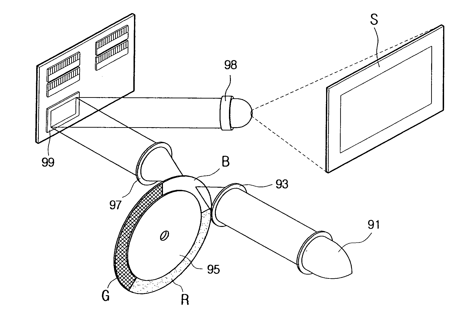
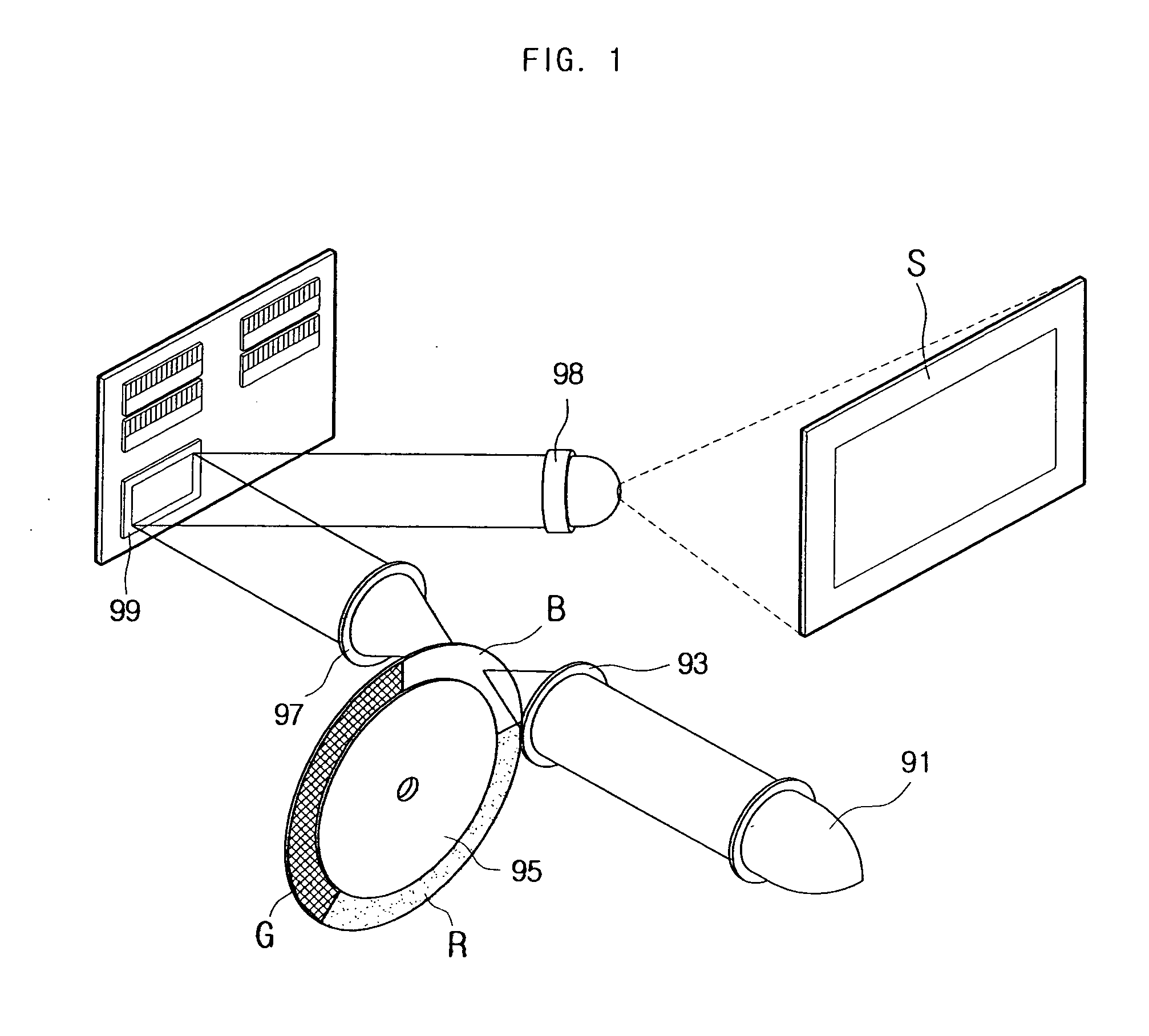
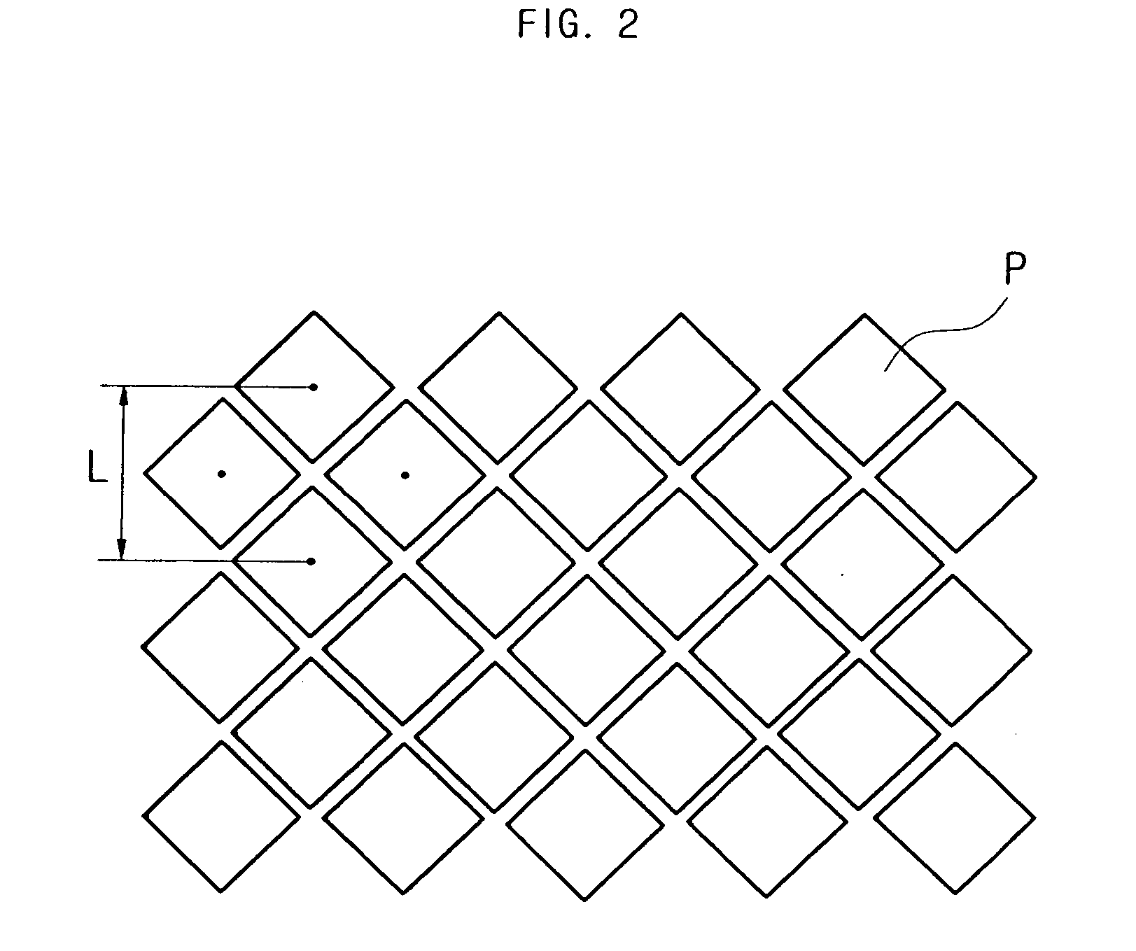
As described above, since conventional image projection devices form a large display simply through the magnified projection of the small original picture, there is the problem that the picture quality is degraded due to the grid pattern formed between each pixel P, as seen in FIG. 2.
Also, there is a problem in that when the picture moves rapidly or where the line of sight of the viewer moves rapidly, the picture is formed on the screen with rainbow colors showing where the contrast ratio is great, for example where there are black stripes on a white background, or with the grid pattern between each pixel notably significant.

Method used


Image

  • Tilting device and operation method thereof
  • Tilting device and operation method thereof
  • Tilting device and operation method thereof

Examples


Embodiment Construction

[0045] Reference will now be made in detail to the embodiments of the present general inventive concept, examples of which are illustrated in the accompanying drawings, wherein like reference numerals refer to the like elements throughout. The embodiments are described below in order to explain the present general inventive concept by referring to the figures.

[0046] As seen in FIGS. 3 and 4, the tilting device according to an embodiment of the invention comprises a mirror 60 which reflects light, a mirror holder 30 which vibrates with the mirror 60, an elastic element 50 positioned between the mirror 60 and the mirror holder 30, a securing element 40 which secures the mirror 60 to the mirror holder 30, a holder support part 20 which supports the mirror holder 30 to allow vibration, and a base holder 10 which secures the holder support part 20. Although it is not shown in FIG. 3, the tilting device also comprises a driving part (see FIG. 9), which provides driving power to the mirro...


PUM


Abstract

A tilting device and an operation method thereof are disclosed. The tilting device according to the invention comprises a mirror positioned on a light path which periodically tilts light, a mirror holder joined to the mirror which vibrates with the mirror, a holder support part supporting the mirror holder to allow vibration, and a driving part which provides driving power to the mirror holder, wherein the driving part forms a predetermined angle with the mirror holder and causes vibration about the intersecting first axis and second axis. Thus, the tilting device may not only provide a smooth and natural display but also reduce the number of digital micro-mirror pixels.

Description

CROSS-REFERENCE TO RELATED APPLICATIONS [0001] This application claims the benefit of Korean Patent Application No. 2005-96769 filed with the Korea Industrial Property Office on Oct. 14, 2005, the disclosure of which is incorporated herein by reference. BACKGROUND OF THE INVENTION [0002] 1. Field of the Invention [0003] The present invention relates to a tilting device and an operation method thereof. [0004] 2. Description of the Related Art [0005] An image projection device using Digital Light Processing (DLP), in which the mosaic phenomenon in pixels, a problem in regular Liquid Crystal Display (LCD) imaging devices, is eliminated to improve the ability to reproduce original colors, is used widely in theaters, conference rooms, and projection TV's, etc. The image projection device can be divided into a Front Projection device and a Rear Projection device according to the projection method. [0006] The Front Projection device adopts the method of projecting image signals from the fr...

Claims


Application Information

Patent Timeline
IPC IPC(8): G02B23/00
CPCG02B26/085H04N9/3114H04N9/312H02N2/02H04N1/044
Inventor MOON, YANG-HOLEE, CHIL-SUNGPARK, KYOUNG-SHINCHOI, DONG-WONKIM, JAE-KYUNG
Owner SAMSUNG ELECTRO MECHANICS CO LTD
Why Eureka
Try Eureka