Module assembly for locking and unlocking a battery of an electronic device

a technology of electronic devices and modules, applied in the direction of portable computer details, electric apparatus casings/cabinets/drawers, instruments, etc., can solve the problems of inability to upgrade, inability to meet the needs of users, so as to reduce the quantity of molds, reduce the effect of manufacturing cost and simplify the process of material planning, material management and inventory

Inactive Publication Date: 2007-04-26
INVENTEC CORP
View PDF19 Cites 25 Cited by
  • Summary
  • Abstract
  • Description
  • Claims
  • Application Information

AI Technical Summary

Benefits of technology

[0014] Therefore, it is a primary objective of the present invention to overcome the foregoing shortcomings of the two different types of components including the automatic latch button and passive latch button at the lower chassis of a prior art notebook computer. The notebook computer includes a receiving groove disposed at the lower chassis, and the interior of the lower chassis includes a first limit section and a second limit section disposed on both sidewalls adjacent to the receiving groove; wherein the first limit section includes an automatic latch button comprised of a latch and a button body, and the second limit section includes a passive latch button comprised of a latch and a button body, and these two latches include an embedding hole each, and a lock tongue is installed at an end of the two latches and exposed from both ends of the receiving groove. A rod body is extended horizontally from the other end of the two latches; wherein a flange is disposed on the external edge of the rod body of the automatic latch button for connecting an elastic element, and a flange is disposed on the external edge of the rod body on the passive latch button, such that the flange presses against at least one protrusion on another end of the second limit section, and one side of the two button bodies is exposed from the lower chassis, and an embedding body is disposed on another surface of the two button bodies to be latched into the embedding hole of the two latches. Therefore, the components of the automatic latch button and the passive latch button constitute a common module assembly, not only reducing the quantity of molds to effectively lower the manufacturing cost, but also simplifying the material planning, material management and inventory by the common module assembly.

Problems solved by technology

Unlike the desktop computers offering different brands and models for consumer's choice, notebook computers sacrifice the possibility of upgradeability.
However, the lightweight, thin, short and compact design of notebook computers has advantages over the desktop computers, and their mobility and convenience is incomparable by desktop computers.
However, the functions and applications of this type of notebook computers are not as good as the previous type.
If the passive latch button is set in a locked status, then switching the automatic latch button cannot remove the rectangular insertable battery.
In the meantime, the processes planning material, and managing materials and inventory will become more complicated, and even worse, the assembler may have difficulties of determining the materials or make mistakes easily.
Viewing from the worldwide distributions and sales of notebook computers, we understand that if the manufacturers cannot effectively overcome the foregoing shortcomings, they cannot gain a good market share in the severe competition, and thus their market competitiveness will drop.
Without a good design to improve the foregoing shortcomings, a manufacturer hardly can succeed, and thus finding a way to improve the prior art and the competitiveness demands immediate attentions.

Method used


Image

  • Module assembly for locking and unlocking a battery of an electronic device
  • Module assembly for locking and unlocking a battery of an electronic device
  • Module assembly for locking and unlocking a battery of an electronic device

Examples


Embodiment Construction

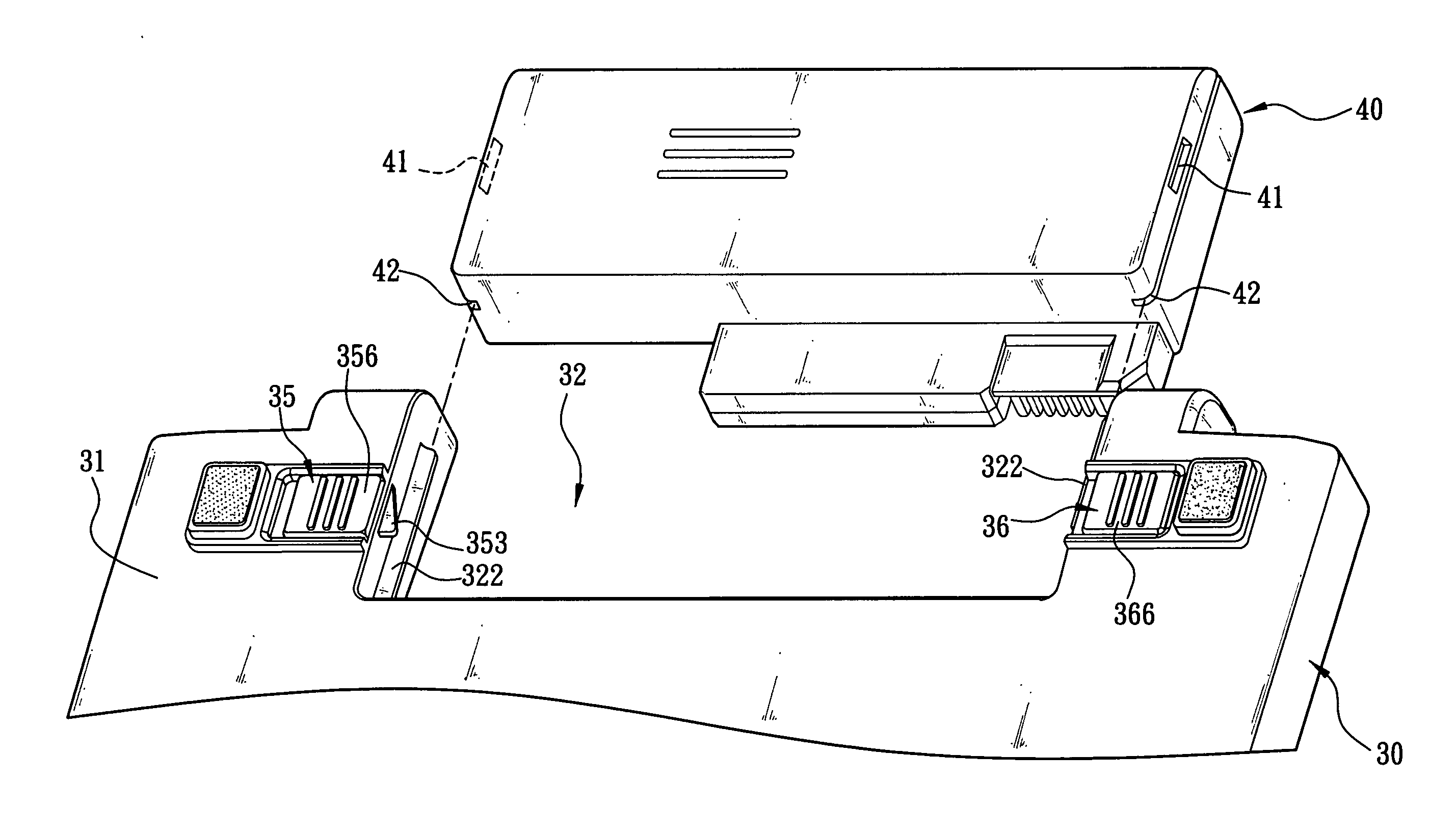
[0020] Referring to FIGS. 3 and 4 for the module assembly for locking and unlocking a battery of an electronic device according to a preferred embodiment of the present invention, an electronic device such as a notebook computer is used for illustration. The notebook computer 30 comprises a lower chassis 31, a narrow long receiving groove 32 disposed on one side of the lower chassis 31, and a first limit section 33 and a second limit section 34 separately disposed inside the lower chassis 31 and proximate to both sidewalls of the receiving groove 32 as shown in FIG. 3; wherein the first limit section 33 includes an automatic latch button 35, and the automatic latch button 35 comprises a latch 351 and a button body 356, and the latch 351 includes an embedding hole 352 thereon, and one end of the latch 351 includes an inclined lock tongue 353 exposed from an end of the receiving groove 32 and a rod body 354 extended horizontally from another end of the latch 351. The rod body 354 incl...


PUM


Abstract

The present invention is to provide a module assembly for locking and unlocking a battery of an electronic device, which including a receiving groove deposited at a lower chassis having a first and a second limit section on both sidewalls; wherein an automatic latch button deposited on the first limit section and a passive latch button deposited on the second limit section both comprise a latch with an embedding hole, a button body, a lock tongue and an extended rod body, a flange is disposed on the rod body of the automatic latch button for connecting an elastic element, a flange is disposed on the rod body of the passive latch button for pressing against at least one protrusion on the second limit section, one side of each button body is exposed from the lower chassis, and an embedding body is disposed on another side of each button body to be latched into the embedding hole of each latch.

Description

FIELD OF THE INVENTION [0001] The present invention relates to a module assembly for locking and unlocking a battery of an electronic device, and more particularly to a module assembly disposed at the lower chassis of an electronic device (e.g. notebook), which having an automatic latch button and a passive latch button for locking and unlocking. BACKGROUND OF THE INVENTION [0002] In recent years, the computer industry is blooming, and the notebook computer technology is improved constantly by engineers and gradually appreciated by consumers. As the price of notebook computers drops year after year, notebook computers are used extensively. Unlike the desktop computers offering different brands and models for consumer's choice, notebook computers sacrifice the possibility of upgradeability. However, the lightweight, thin, short and compact design of notebook computers has advantages over the desktop computers, and their mobility and convenience is incomparable by desktop computers. [...

Claims


Application Information

Patent Timeline
Patent Type & Authority Applications(United States)
IPC IPC(8): G06F1/16
CPCG06F1/1616G06F1/1635G06F1/1679
Inventor WU, YAZ-TZUNG
Owner INVENTEC CORP
Why Eureka
Try Eureka