Contrast enhancement for optical recording

Inactive Publication Date: 2007-04-26
ARMI PROD
View PDF27 Cites 0 Cited by
  • Summary
  • Abstract
  • Description
  • Claims
  • Application Information

AI Technical Summary

Benefits of technology

[0043] In another aspect, in general, a method of writing information in a recordable medium includes applying an en

Problems solved by technology

At the same time, the energy released in the reaction may cause a micro-rupture mark on the disc that also reduces the reflectivity.
For exa

Method used


Image

  • Contrast enhancement for optical recording
  • Contrast enhancement for optical recording
  • Contrast enhancement for optical recording

Examples


Example

1 Optical Recording System

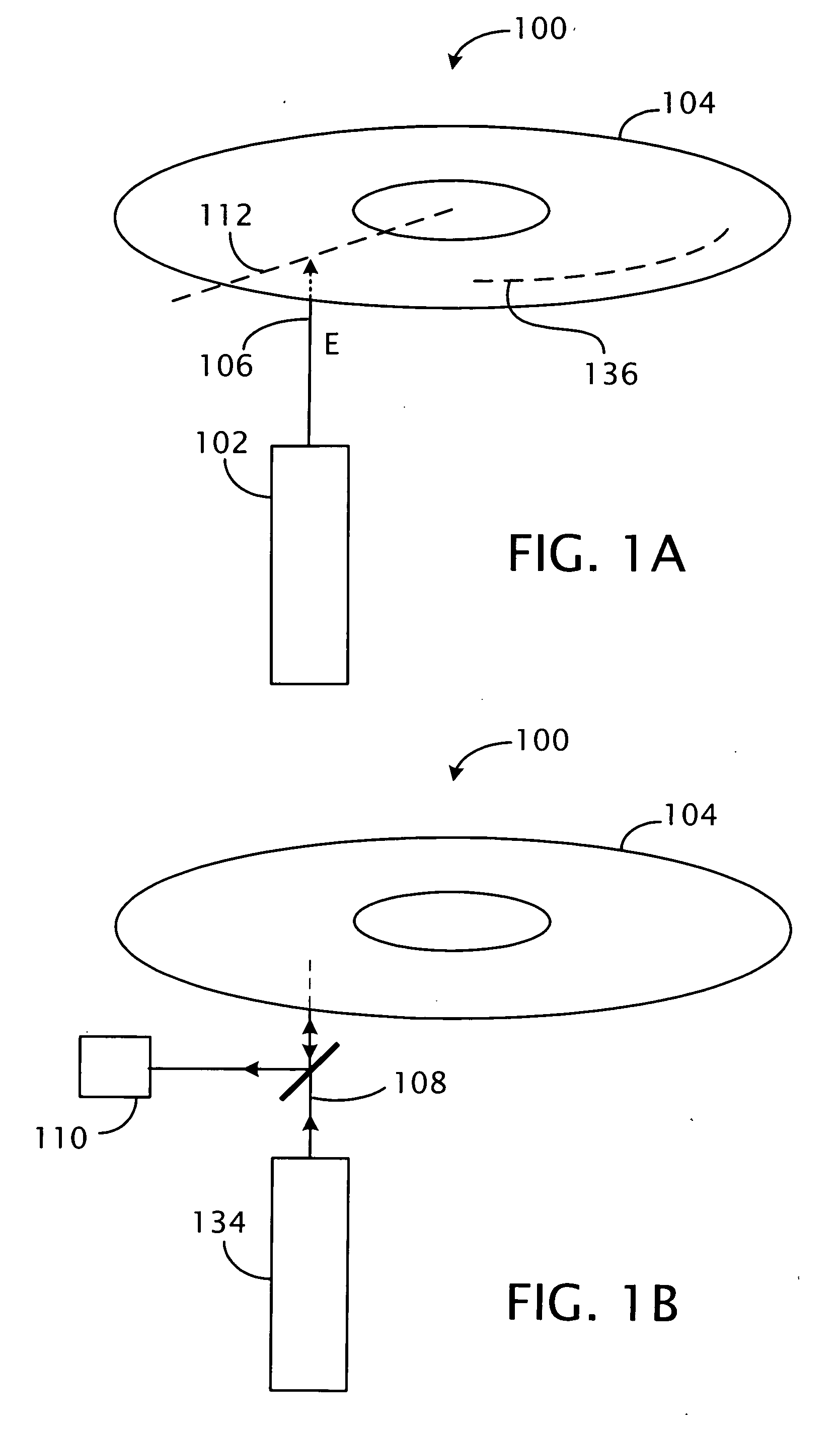
[0128] Referring to FIG. 1A, in an example of an optical recording system, data is written to a recordable disc 104 by applying energy to an inscription layer in the recordable disc 104. The energy is applied using a write beam 106, which can be a laser beam emitted from a semiconductor laser diode 102. The energy induces a change in an optical property of the inscription layer of the disc, in this case resulting in a change in overall reflectivity of the disc as a whole (i.e., at the external surface of the disc at which a read beam is incident) with respect to the read beam.

[0129] Referring to FIG. 1B, when reading the data recorded on the recordable disc 104, a read beam 108, which can be a laser beam emitted from a semiconductor laser diode 134, is focused on the inscription layer, and a photo detector 110 detects the read beam reflected from the recordable disc 104. Because the amount of reflected light is different between regions that have been in...


PUM


Abstract

A recordable medium includes an inscription layer and a contrast enhancing layer. The inscription layer has at least two sub-layers that combine upon application of a write power, the inscription layer having a reflectivity R1 before application of the write power and a reflectivity R2 after application of the write power. The contrast enhancing layer does not combine with the sub-layers of the inscription layer upon application of the write power. The contrast enhancing layer and the inscription layer together have a reflectivity R3 before application of the write power and a reflectivity R4 after application of the write power, and |R4−R3|>|R2−R1|.

Description

CROSS-REFERENCE TO RELATED APPLICATIONS [0001] This application is related to concurrently filed U.S. patent applications Ser. No.______, titled “Generating Optical Contrast Using Thin Layers” (attorney docket 16233-002001), Ser. No.______, titled “Contrast Inversion for Optical Recording” (attorney docket 16233-003001), Ser. No.______, titled “Micro-resonant Structure for Optical Recording” (attorney docket 16233-005001), Ser. No.______, titled “Generating Optical Contrast Using Thin Layers” (attorney docket 16233-008001), and Ser. No.______, titled “Multiple Recording Structures for Optical Recording” (attorney docket 16233-009001), all of which are herein incorporated by reference. BACKGROUND OF THE INVENTION [0002] This invention relates to contrast enhancement for optical recording. [0003] An optical recording medium stores data by producing optical contrasts in the medium, such as contrasts in reflectivity with respect to a light beam. For example, binary data can be stored (“...

Claims


Application Information

Patent Timeline
IPC IPC(8): B32B3/02
CPCG11B7/24038G11B7/2433G11B7/2531G11B7/2534G11B7/2578G11B2007/24308G11B2007/2431G11B2007/24312G11B2007/2432G11B2007/25706G11B2007/2571G11B2007/25715G11B2007/25716
Inventor WEN-TAI SHUY, GEOFFREYLU, CHENG-JILAI, HSIN-CHENGLEE, FANG-YUYEN, KO-FU
Owner ARMI PROD
Why Eureka
Try Eureka