Implant with one piece swivel joint

a swivel joint, one-piece technology, applied in the field of implants, can solve the problems of inability to accommodate axial compressive load strength and extent, and achieve the effect of a certain degree of mobility and flexibility, and inherent elasticity

Active Publication Date: 2007-04-26
BIEDERMANN TECH GMBH & CO KG
View PDF17 Cites 25 Cited by
  • Summary
  • Abstract
  • Description
  • Claims
  • Application Information

AI Technical Summary

Benefits of technology

[0017] The material for the preferably one-piece-manufactured base body, i.e. especially the disc and ring elements or ligaments of the film hinges, may be selected from different materials. Especially, all biocompatible metals, metal alloys and polymers are suitable. Due to the structure of th

Problems solved by technology

Although these solutions yield very good results with regards the attainable flexibility, deficits con

Method used


Image

  • Implant with one piece swivel joint
  • Implant with one piece swivel joint
  • Implant with one piece swivel joint

Examples


Embodiment Construction

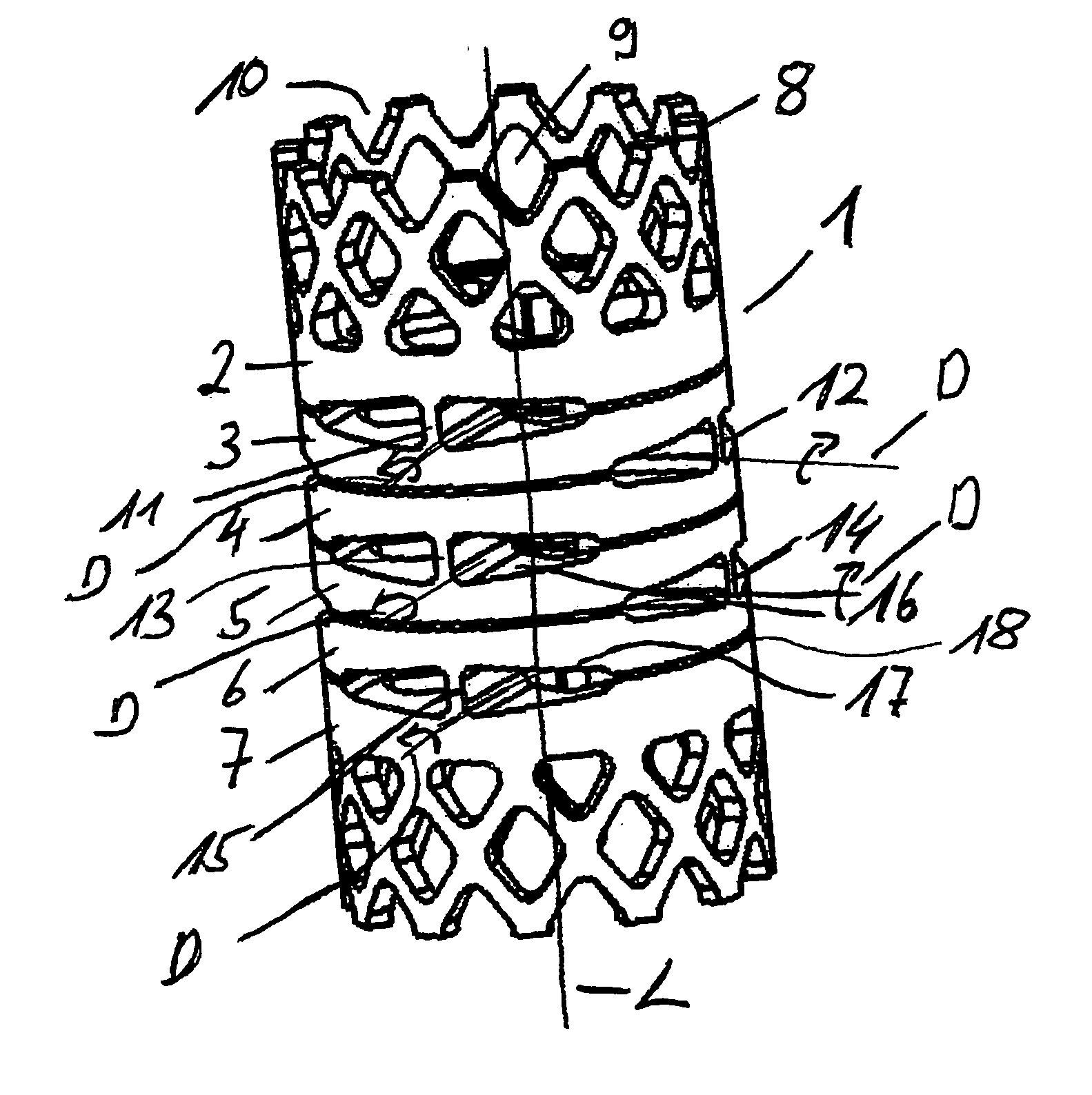
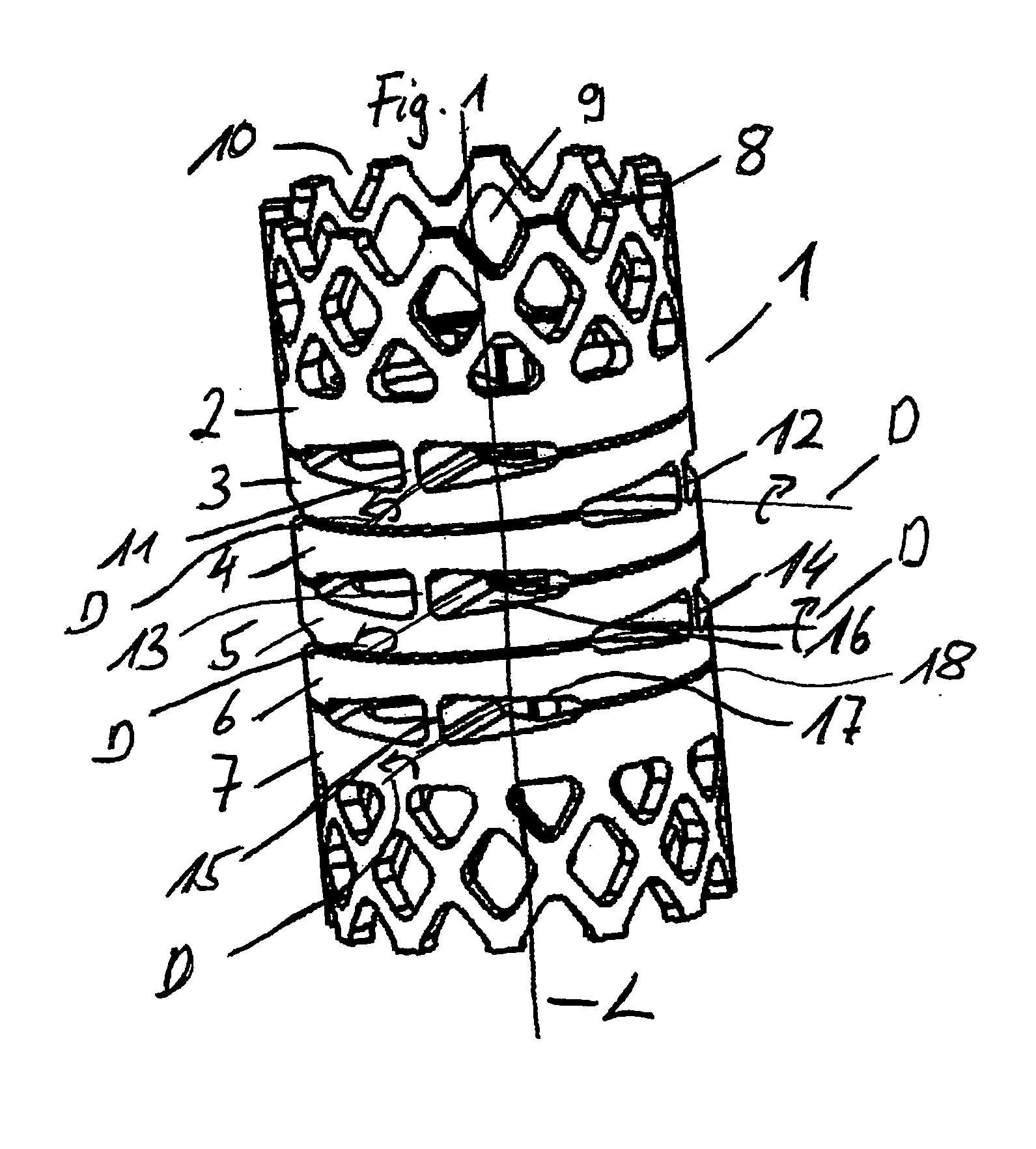
[0040]FIG. 1 is a perspective view of a first embodiment of an implant of the invention in the form of a placeholder for a spinal column.

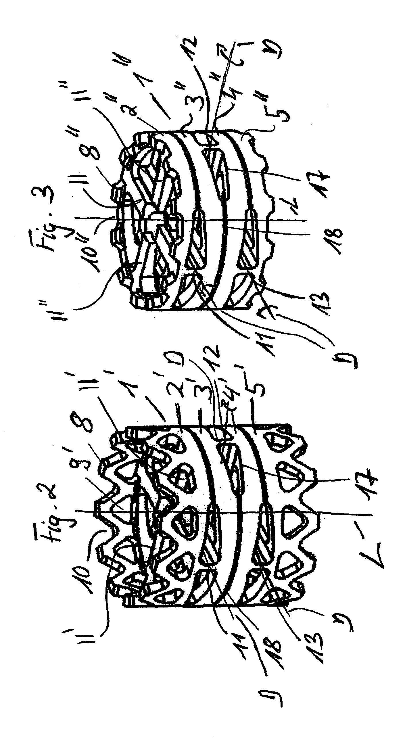
[0041] The placeholder 1 has a generally cylindrical tubular base body, which is subdivided into six discs or ring elements 2 to 7 (referred to herein as ring elements), which are arranged on top of each other along the longitudinal axis L, which is simultaneously the primary load axis L. On the outwardly projecting ends of the two end ring elements 2 and 7 are connecting elements 8 to 10, which are formed from blunted serrations 8, diamond-like cut outs or triangular cutouts 9 and triangular recesses 10 between the blunted serrations 8. These connecting elements 8 to 10 serve to engage and grow together with adjacent tissue, cartilage or vertebrae. With the connecting elements 8 to 10, a secure arrangement of the placeholder 1 in the spinal column is ensured.

[0042] Between each of the disc or ring elements 2 to 7 are provided two ligaments exten...


PUM


Abstract

An implant for permanent or temporary introduction into the human or animal body includes a base body for connecting spaced body parts and/or other implant components, said implant having a load axis, along which primarily tensile and/or compressive forces are transmissible, with at least one rotary axis formed at right angle to the load axis, said rotary axis facilitating at least limited bending of the base body about the rotary axis, especially of the ends of the base body arranged along the load axis, with the at least one rotary axis being defined by a swivel joint, which is formed in one-piece at the base body.

Description

RELATED APPLICATION(S) [0001] The present application claims the benefit of U.S. Provisional Patent Application Ser. No. 60 / 730,587, filed Oct. 26, 2005, and claims priority from EP 05110043, filed Oct. 26, 2005, the entire disclosures of which are incorporated herein by reference.BACKGROUND OF THE INVENTION [0002] The present invention relates to an implant for permanent or temporary incorporation into the human or animal body and a placeholder for vertebrae, an intervertebral disc replacement or a connecting rod for pedicle screw arrangements as well as a stabilization system made from these components. [0003] In modem medicine, use of implants to replace parts of the human skeleton following illness, injury or age-related wear-phenomena is widespread. Thus, it is known, for example, in the case of spinal injury such as breaks or when parts of the spinal column are attacked by a tumour, corresponding vertebrae are replaced by placeholders. Such placeholders are described, for exam...

Claims


Application Information

Patent Timeline
IPC IPC(8): A61F2/44
CPCA61B17/7001A61B17/7004A61B17/7026A61B17/7037A61B17/86A61F2/44A61F2230/0069A61F2/4425A61F2002/30235A61F2002/30571A61F2002/30777A61F2002/30787A61F2002/30841A61F2/442A61F2/28
Inventor BIEDERMANN, LUTZMATTHIS, WILFRIEDHARMS, JURGEN
Owner BIEDERMANN TECH GMBH & CO KG
Why Eureka
Try Eureka