Apparatus and method for balancing a printing roller having an image producing area on its outer surface

a printing roller and image producing area technology, applied in the field of printing rollers, can solve the problems of printing rollers in printing presses, particularly, becoming unbalanced, printing rollers becoming unbalanced, etc., and achieve the effect of convenient use and manufacture, and low cos

Inactive Publication Date: 2007-05-03
VAN DENEND MARK E
View PDF17 Cites 19 Cited by
  • Summary
  • Abstract
  • Description
  • Claims
  • Application Information

AI Technical Summary

Benefits of technology

The technical effect of this patent is to describe an apparatus and process for balancing a printing roller by removing material from its surface or adding new material to create balance spots on the roller. This can be done quickly and easily with minimal expense.

Problems solved by technology

The technical problem addressed by this patent is how to prevent unevenness and instability when printing images onto flexible materials using flexographic printing methods.

Method used


Image

  • Apparatus and method for balancing a printing roller having an image producing area on its outer surface
  • Apparatus and method for balancing a printing roller having an image producing area on its outer surface
  • Apparatus and method for balancing a printing roller having an image producing area on its outer surface

Examples


second embodiment

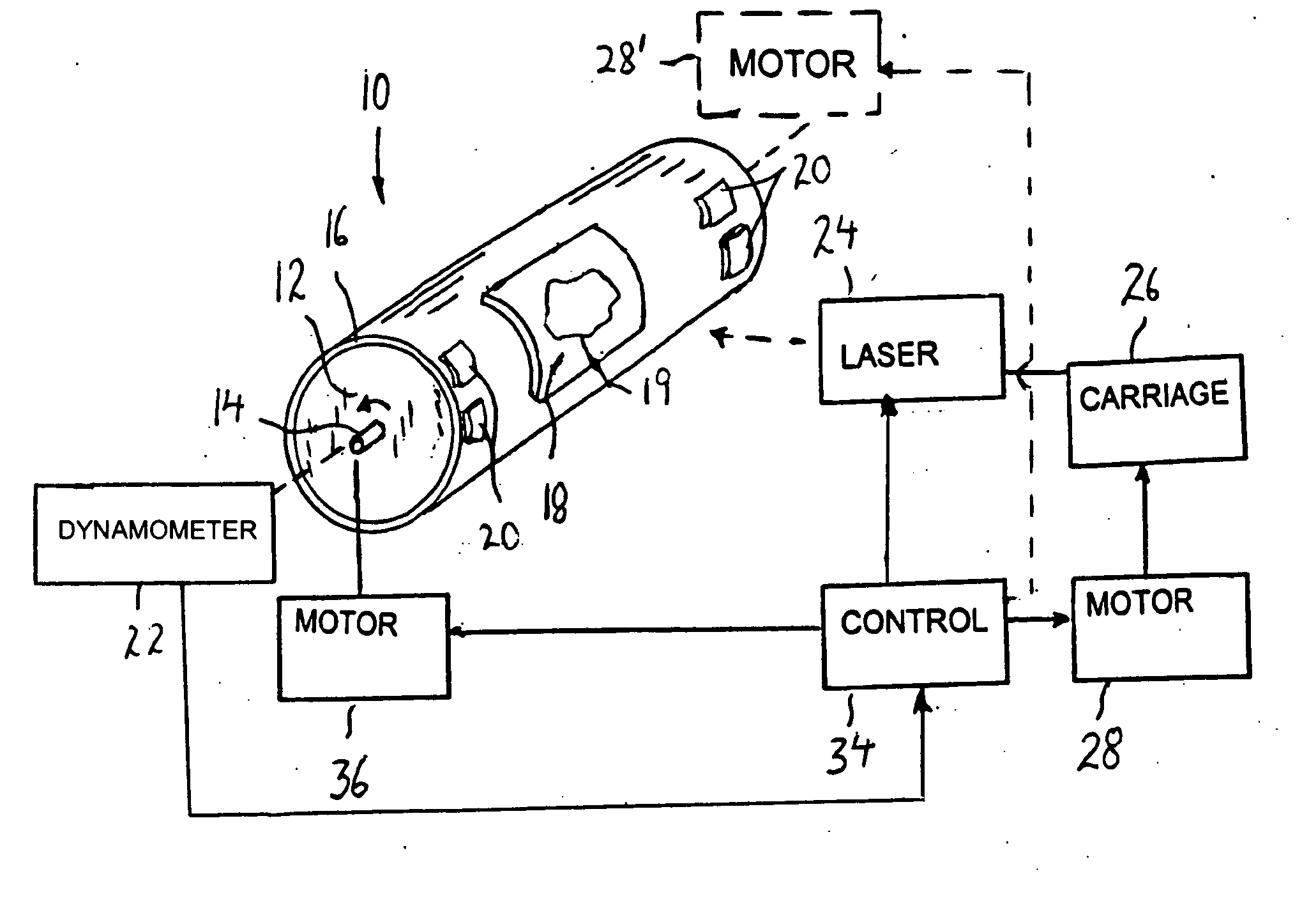
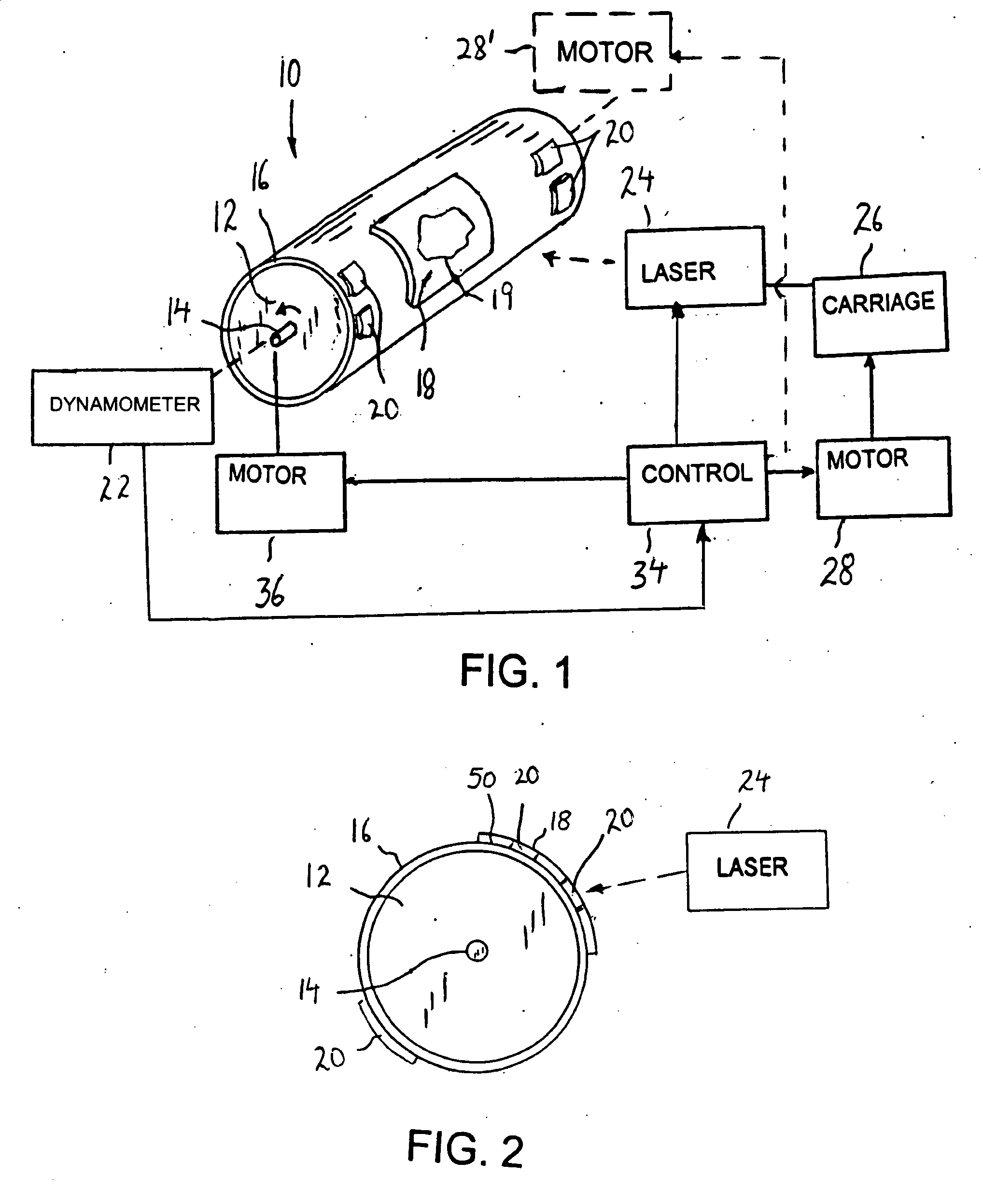
[0047] Referring now to FIG. 4, there is shown the present invention, in which like elements are identified by the same numerals, and a description of the common elements is not provided for the sake of brevity.

[0048] Specifically, in FIG. 4, instead of using a dynamometer to detect any out of balance of printing roller 10, a separate laser 24′ focuses a beam of light 30 that is bounced off the outer surface of cylindrical roller 12 or sleeve 16, and is received by a detector 32, such as an optical detector, that produces the unbalance signal. Alternatively, detector 32 can provide its own source of light against cylindrical roller 12 or sleeve 16, which is then bounced off the same and received by detector 32. For example, detector 32 can include a conventional photodiode which directs light against cylindrical roller 12 or sleeve 16, and a photodetector which detects the light reflected back therefrom. Generally, any signal waves in the electromagnetic spectrum can be used for suc...

third embodiment

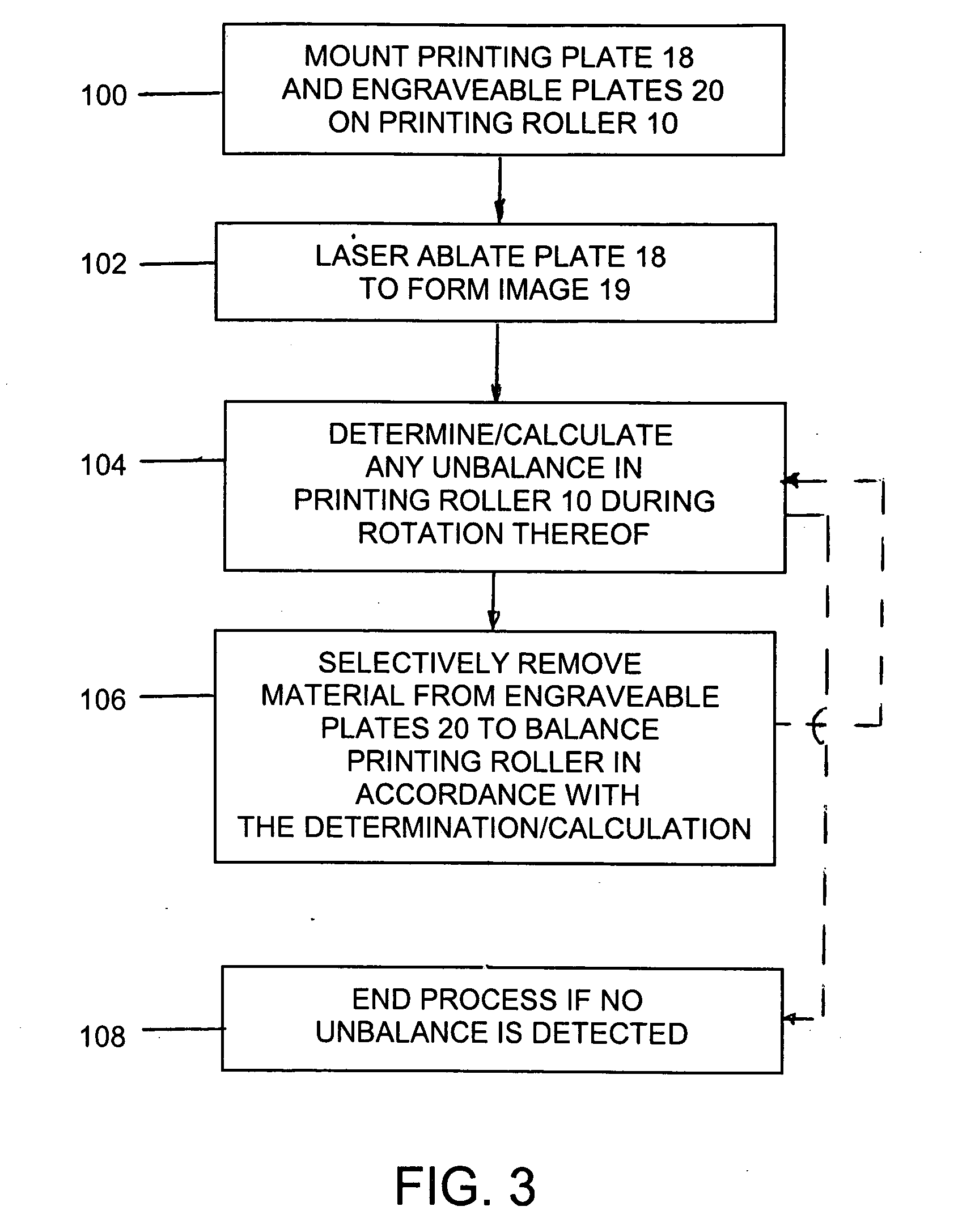
[0057] For example, in this third embodiment, assuming that printing roller 10 is in balance, then the center of mass thereof should be the geometric center. However, where there are other elements, such as sleeve 16, printing plates 18, engraveable plates 20, and any coating, the center of mass will change. Thus, if mass is removed from printing roller 10, then the center of the net mass M will also change. As a result, the calculation then determines further ablation that normally is performed outside of image producing area 19, in order to bring the center of mass back to the same position the geometric center discussed above when assuming that printing roller 10 was in balance, in order to balance printing roller 10.

[0058] If printing roller 10 is in balance prior to ablation, to find the center of gravity of printing roller 10, the mass mi of the removed material must be known and the xi, yi and zi coordinates of the center of gravity of each area of the material removed must b...


PUM

PropertyMeasurementUnit
Weightaaaaaaaaaa
Speedaaaaaaaaaa
Areaaaaaaaaaaa

Abstract

Apparatus for balancing a printing roller having an image producing area thereon, includes a detector for detecting any unbalance of the printing roller during rotation thereof. A computer determines weight adjustments of the printing roller that are required to correct the unbalance, in response to the detection. A laser is controlled by the computer to remove material, in response to the determination, from at least one engraveable plate mounted on the outer surface of the printing roller or from the printing roller itself, in an area outside of the image producing area, in order to balance the printing roller.

Description


Claims


Application Information

Patent Timeline
Owner VAN DENEND MARK E
Why Eureka
Try Eureka