

Sealed container lid of vacuum valve operation type
- Summary
- Abstract
- Description
- Claims
- Application Information
AI Technical Summary
Benefits of technology
Problems solved by technology
Method used
Image

Examples
Embodiment Construction
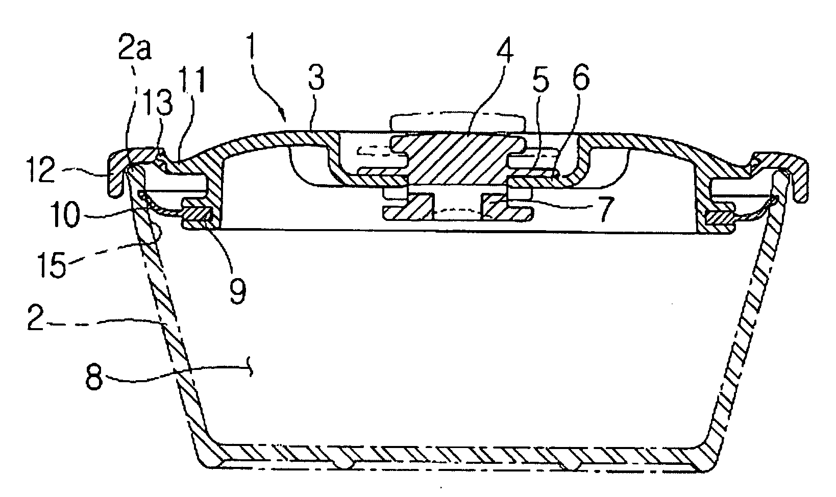
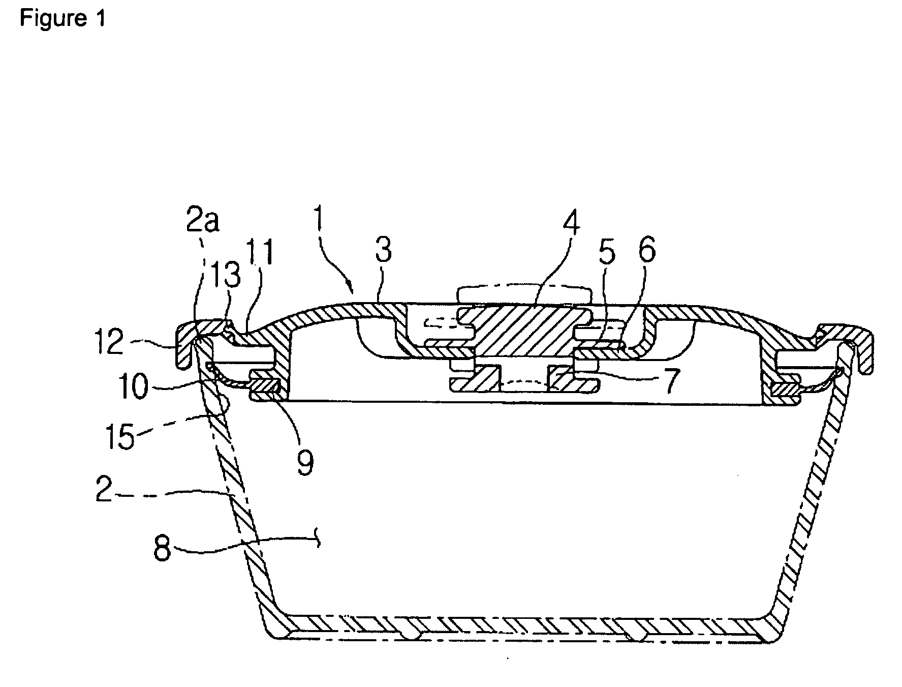
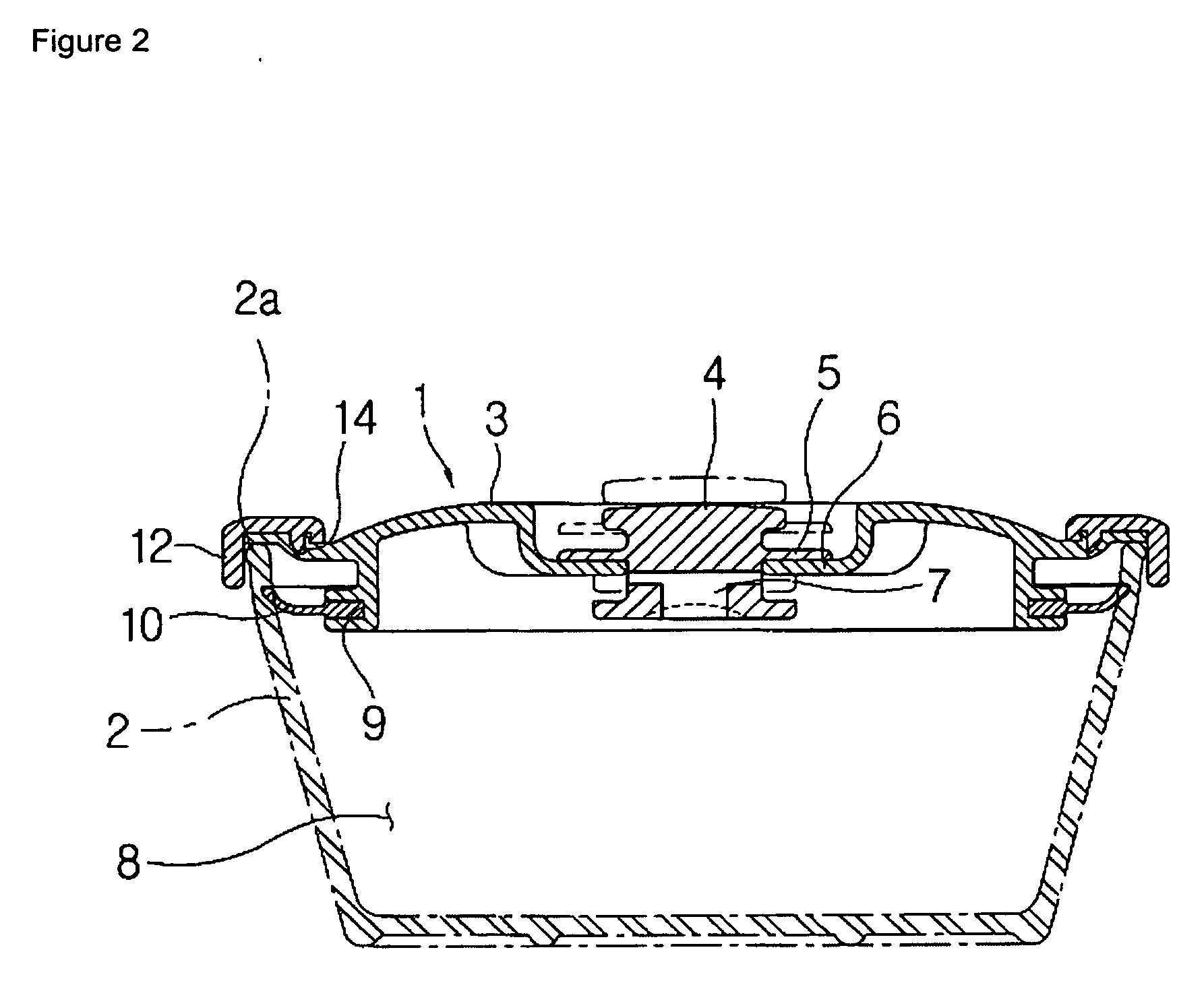
[0015]FIG. 1 is a view illustrating a sealed container lid of a vacuum valve operation type according to the present invention, and FIG. 2 is a view illustrating a dual injection structure of a sealed container lid of a vacuum valve operation type according to an embodiment of the present invention.
[0016] In the drawings, reference numeral 1 represents a container lid, and 2 represents a container body in which the container lid 1 is opened and closed.
[0017] A vacuum valve 4 for an opening and closing operation of a lid is engaged at a body 3 of the container lid 2. When a valve seat 5 of the vacuum valve 4 is lifted off the valve seat 6, the interior 8 of the container body 2 is opened through a valve hole 7 with respect to the outside. When it is pressed and is closely contacted with the valve seat 6, the valve hole 7 is closed, and the interior 8 of the container body 2 is disconnected with the outside.
[0018] A circular groove 9 is formed at the body 3 in a horizontal directio...
PUM
 Abstract
Description
Claims
Application Information