
Grommet

Active Publication Date: 2010-12-09
FORD GLOBAL TECH LLC
View PDF11 Cites 14 Cited by
  • Summary
  • Abstract
  • Description
  • Claims
  • Application Information

AI Technical Summary

Benefits of technology

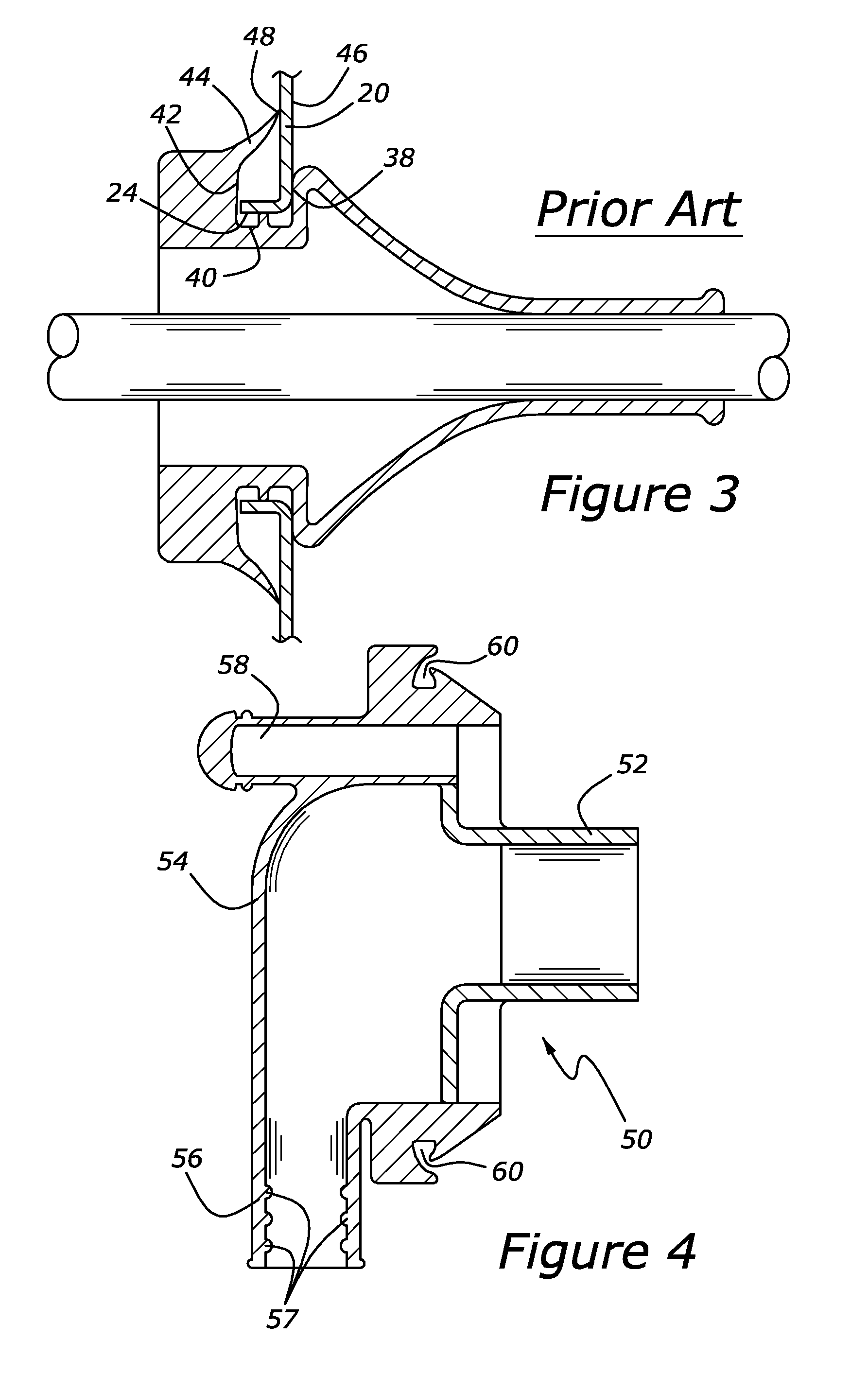
[0014]An advantage of the present development is that lips adjacent to the channel overlap by at least the thickness of the panel to which it is to be engaged, thereby providing a strong sealing force between the lop and the panel. This overlap exerts a strong force to seal the panel by virtue of the tips of the lips pressing on either side of the panel. A third seal is provided between the bottom of the channel and the opening surface of the panel when the size and shape of the panel opening is equally sized and shaped to match the channel in the grommet. In this way, a friction seal is formed between the inside surface of the panel opening and the bottom surface of the channel. This provides a triple seal to prevent ambient fumes, dust, air, noise, etc. from passing through the panel in the vicinity of the opening.
[0015]Yet another advantage of the present development is that by providing a wide bottom surface of the channel and an overlap of the sealing lips, a single grommet is capable of engaging with a flanged or non-flanged panel with sufficient sealing force. By doing so, the number of different parts that a manufacturer purchases is reduced. Parts complexity and the number of parts that are inventoried are also reduced.
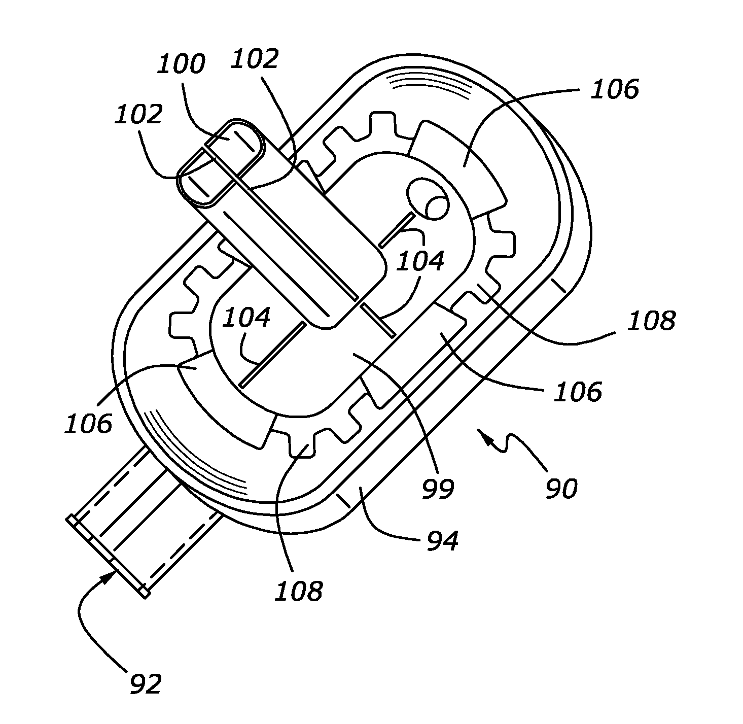
[0016]The present development yields another advantage in that by sawing the slits in the tubular portions of the grommet, the resulting slit is smaller in width than that which can be molded in place. As described below in more detail, the purpose of the slits is to yield a greater flexibility in the grommet application. In some applications, the slits are not used because the wiring harness passing through the tubular portion simply traverses straight through the tube of the grommet. In such cases, the tubular portion is taped up and the sawed slits fit together with little or no gap yielding a tight seal. In other applications, subsets of the wires of the wiring harness are splayed out due to packaging constraints. In one example, a subset of the wires is routed along the panel and thus cannot accommodate traversing through the tube of the grommet prior to attaining such orientation. Furthermore, various subsets of the wires of the wiring harness may be routed in different directions immediately on the other side of the panel.

Problems solved by technology

In one example, a subset of the wires is routed along the panel and thus cannot accommodate traversing through the tube of the grommet prior to attaining such orientation.
However, the tubular portions on either side of a molded slit do not mate well and provide a less than optimal seal when taped.
Also, molded slits are wider and don't seal well.

Method used


Image

  • Grommet
  • Grommet
  • Grommet

Examples


Embodiment Construction

[0026]As those of ordinary skill in the art will understand, various features of the embodiments illustrated and described with reference to any one of the Figures may be combined with features illustrated in one or more other Figures to produce alternative embodiments that are not explicitly illustrated or described. The combinations of features illustrated provide representative embodiments for typical applications. However, various combinations and modifications of the features consistent with the teachings of the present disclosure may be desired for particular applications or implementations. The representative embodiments used in the illustrations relate generally to a grommet adapted to be installed into an opening of a body panel on an automotive vehicle. However, the grommet may be incorporated into various other types of vehicles, such as boats, private airplanes, etc. as well as other applications such as a control room of a plant, a refrigeration unit, as two examples. T...


PUM

PropertyMeasurementUnit
Widthaaaaaaaaaa
Thicknessaaaaaaaaaa
Forceaaaaaaaaaa

Abstract

A grommet providing triple sealing feature when mounted in an opening of a panel is disclosed. When the panel into which the grommet is mounted is between a compartment exposed to ambient conditions and a passenger compartment, a seal minimizes water, fumes, dust, and noise from entering into the passenger compartment. The triple seal, according to an embodiment, provides higher sealing forces than shown previously. The disclosed grommet can be engaged with a flat, non-flanged panel as well as a panel having a flange near the opening. The disclosed grommet has multiple longitudinal slits sawed through a tubular portion of the grommet through which the wiring harness is threaded. The cuts allow a subset of wires to be splayed out from the grommet at a different routing than the remainder of the wires in the wiring harness bundle.

Description

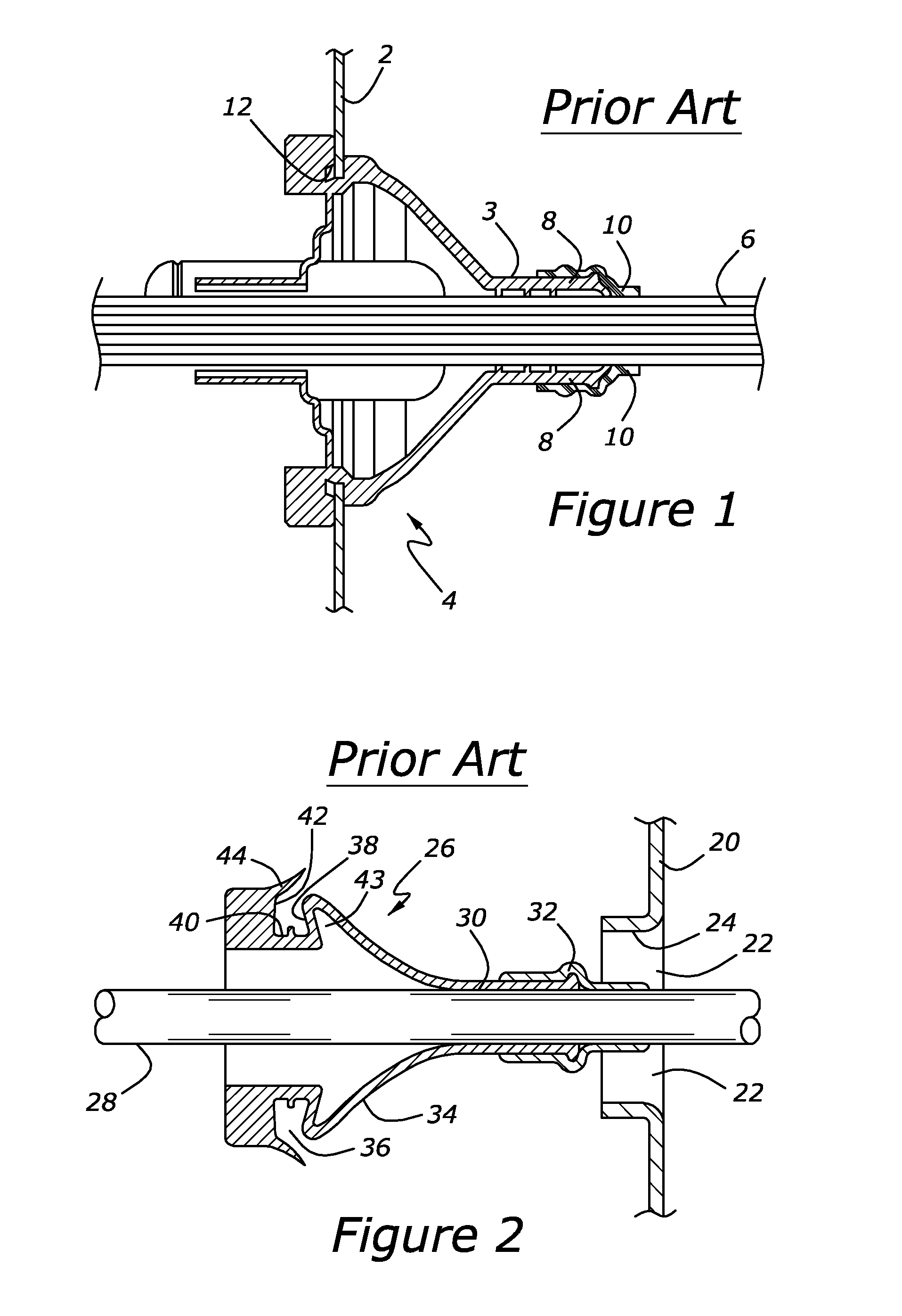
BACKGROUND[0001]1. Technical Field[0002]The present development relates to grommets and more particularly to sealing an opening in a panel.[0003]2. Background Art[0004]In automotive vehicle applications, there are various vehicle body panels through which a wiring harness is passed, such as the firewall or door panels. Typically, an opening is punched, or otherwise formed, in the body panel. A grommet is fitted into the opening, with the grommet having a passage through which the wiring harness can be threaded. A cross-section of a grommet installed into a body panel, according to the prior art, is shown in FIG. 1. A body panel 2 has an opening into which a grommet 4 is installed. Grommet 4 has multiple wires forming a wiring harness 6 passing through a tubular portion 8 of grommet 4. Typically, tape 10 is wrapped around the wiring harness 6. Grommet 4 has a channel 12 (or groove) into which a portion of panel 2 near the opening is held. The opening in panel 2 and channel 12 are siz...

Claims


Application Information

Patent Timeline
IPC IPC(8): H01B17/26H01B19/00
CPCH02G3/22Y10T29/49227Y10T16/063B60R16/0222
Inventor BAYDOUN, MOHAMMED MICHAELDEWITT, ANTONY DOWLING
Owner FORD GLOBAL TECH LLC
Learn More