Paddled rotor spaceblocks

a technology of paddled space blocks and generator rotors, which is applied in the direction of magnetic circuit rotating parts, windings, magnetic circuit shapes/forms/construction, etc., can solve the problems of limiting factors, difficult and expensive forced cooling, and limited power output rating of dynamoelectric machines such as large turbo-generators, so as to promote cooling flow and reduce relative tangential velocity

Active Publication Date: 2007-05-03
GENERAL ELECTRIC CO
View PDF12 Cites 9 Cited by
  • Summary
  • Abstract
  • Description
  • Claims
  • Application Information

AI Technical Summary

Benefits of technology

[0014] The present application further describes a method of promoting a cooling flow in a dynamoelectric machine having a rotor and a number of spaceblocks. The method may include positioning a pair of paddles on one or more of the spaceblocks, rotating the rotor so as to generate the cooling flow with a relative tangential velocity, and deflecting the cooling flow with the paddles so as to reduce the relative tangential velocity such that the cooling flow is largely in an axial direction.
[0015] The present application further describes a dynamoelectric machine cooled by a gas flow. The machine may include a rotor, a number of coil endwindings extending axially beyond the rotor, a number of spaceblocks located about the coil endwinding, and a passageway positioned about one or more of the spaceblocks. One or more of the spaceblocks may include the paddles extending into the passageway so as to deflect the gas flow into an axial direction.

Problems solved by technology

The power output rating of dynamoelectric machines, such as large turbo-generators, is often limited by the ability to provide additional current through the rotor field winding because of temperature limitations imposed on the electrical conductor insulation.
This is especially true in the rotor end region, where direct, forced cooling is difficult and expensive.
As prevailing market trends require higher efficiency and reliability in lower cost, higher-power generators, cooling the rotor end region becomes a limiting factor.
This circulation path results in low heat transfer coefficients especially near the center of the cavity.
Thus, this means for heat removal about the endwindings it is relatively inefficient.
Such systems, however, have only limited usefulness due to the high mechanical stress and fatigue considerations relating to the retaining ring.
If the conventional forced rotor end cooling schemes are used, considerable complexity and cost are added to rotor construction.
These elements again add complexity and cost.
Heat removal is thus limited by the low circulation velocity of the gas in the cavity and the limited amount of the gas that can enter and leave these spaces.

Method used


Image

  • Paddled rotor spaceblocks
  • Paddled rotor spaceblocks
  • Paddled rotor spaceblocks

Examples


Embodiment Construction

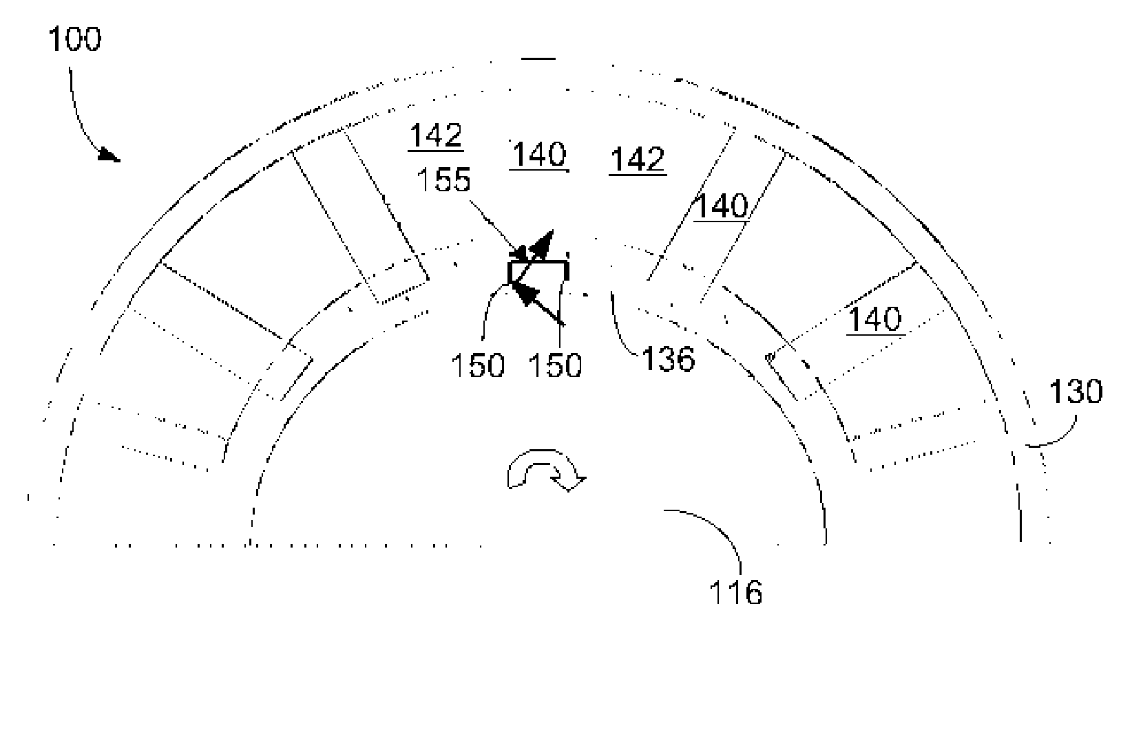
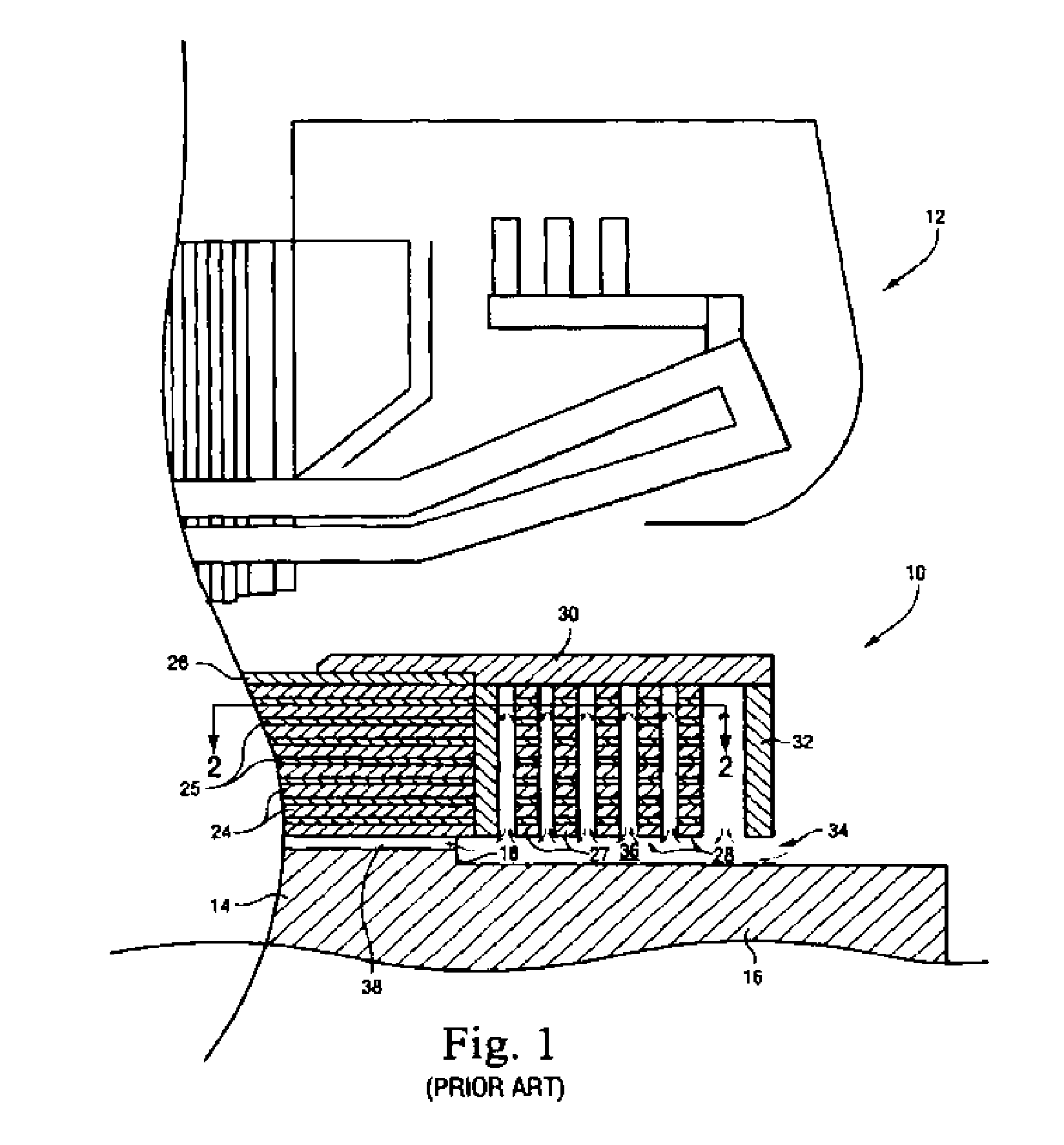
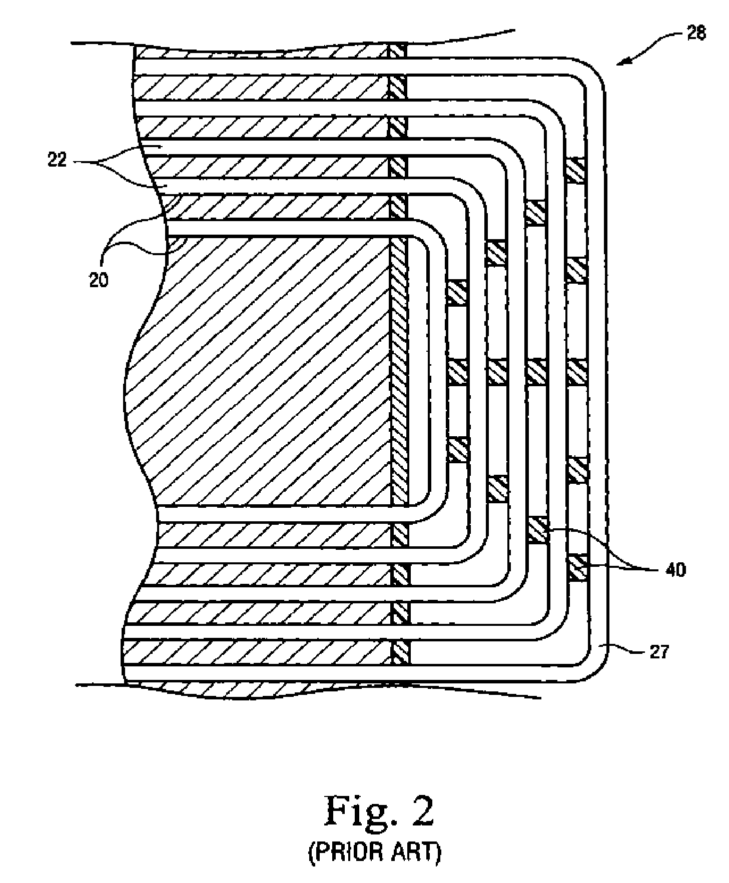
[0025] Referring now to the drawings, in which like numerals refer to like elements throughout the several views, FIGS. 1 and 2 show a rotor 10 for a gas-cooled dynamoelectric machine. The general operation of dynamoelectric machines such as large turbo-generators is well known. The rotor 10 includes a stator 12 surrounding the rotor 10. The rotor 10 includes a generally cylindrical body portion 14 centrally disposed on a rotor spindle 16 and having axially opposing end faces, of which a portion 18 of one end face is shown in FIG. 1. The body portion 18 is provided with a number of circumferentially spaced, axially extending slots 20 for receiving concentrically arranged coils 22. The coils 22 make up the rotor winding. For clarity, only five rotor coils 22 are shown, although several more are commonly used in practice.

[0026] A number of conductor bars 24 may be stacked in each one of the slots 20. Layers of electrical insulation 25 may separate the adjacent conductor bars 24. The ...


PUM


Abstract

A dynamoelectric machine cooled by a gas flow. The machine may include a rotor, an endwinding extending axially beyond the rotor, a spaceblock located about the endwinding, and a passageway positioned about the spaceblock. The spaceblock may include a C-channel extending into the passageway so as to deflect the gas flow into an axial direction.

Description

TECHNICAL FIELD [0001] The present invention relates generally to generator rotors and more particularly relates to enhanced cooling of generator rotors by the use of paddled spaceblocks. BACKGROUND OF THE INVENTION [0002] The power output rating of dynamoelectric machines, such as large turbo-generators, is often limited by the ability to provide additional current through the rotor field winding because of temperature limitations imposed on the electrical conductor insulation. Effective cooling of the rotor winding contributes directly to the output capability of the machine. This is especially true in the rotor end region, where direct, forced cooling is difficult and expensive. As prevailing market trends require higher efficiency and reliability in lower cost, higher-power generators, cooling the rotor end region becomes a limiting factor. [0003] Turbo-generator rotors typically have concentric rectangular coils mounted in slots in a rotor. The end portions of the coils (common...

Claims


Application Information

Patent Timeline
Patent Type & Authority Applications(United States)
IPC IPC(8): H02K1/32H02K1/22H02K3/46
CPCH02K3/24H02K3/505H02K3/51H02K1/22H02K3/46
Inventor SALAMAH, SAMIR A.PARSANIA, NISHANT
Owner GENERAL ELECTRIC CO
Why Eureka
Try Eureka