Centrifugal fan diffuser

a centrifugal fan and diffuser technology, applied in the direction of machines/engines, stators, liquid fuel engines, etc., can solve the problems of less efficient conversion of velocity to static pressure, complicated installation, and inconvenient installation, so as to reduce the effect of tangential velocity and reduce the amount of material needed

Active Publication Date: 2005-06-30
ACOUSTIFLO
View PDF40 Cites 7 Cited by
  • Summary
  • Abstract
  • Description
  • Claims
  • Application Information

AI Technical Summary

Benefits of technology

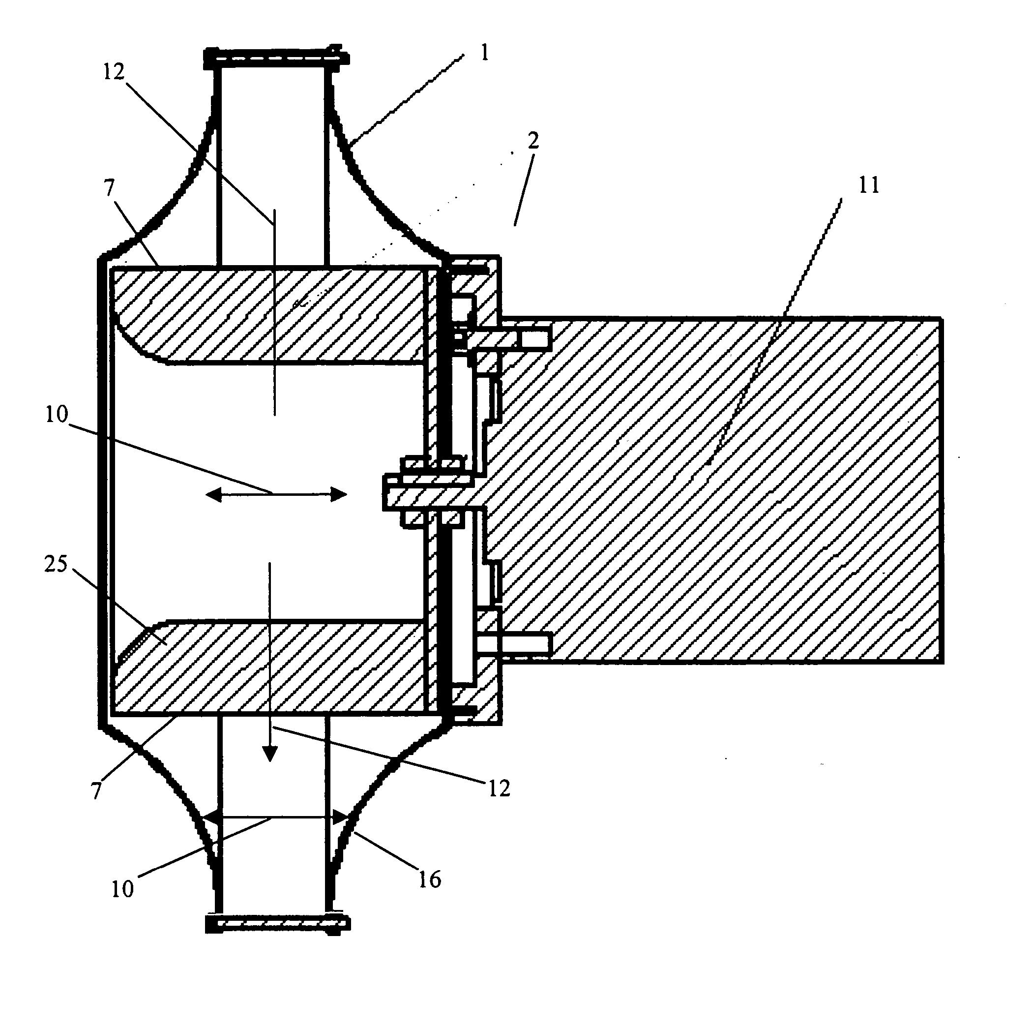
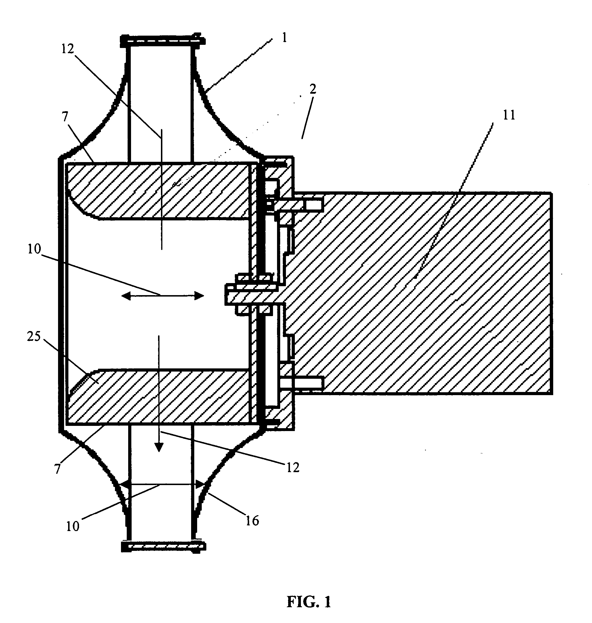
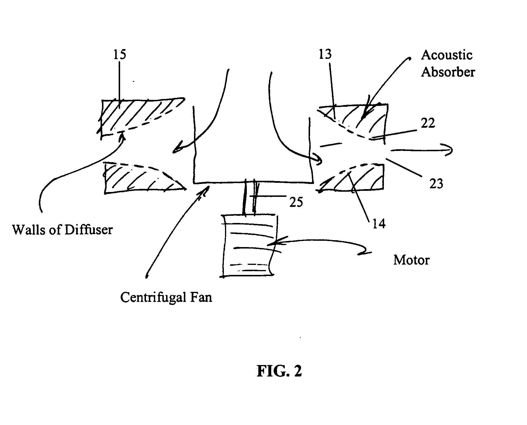
[0021] The present invention includes a variety of aspects which may be combined in different ways. In one basic form the invention discloses the use of an inventive vaneless diffuser extra-radially of a centrifugal fan, wherein the diffuser effects an optimal transformation of velocity pressure into static pressure of a fluid such as air impelled by a centrifugal fan by decreasing the tangential velocity of that fluid as it travels through the diffuser, while adjusting the internal sides of the diffuser so as to avoid recirculation of air output from the diffuser back into the diffuser. Such diffuser may effect such a decrease in tangential velocity by radially extending the interface through which impelled air is output from the diffuser to a downflow fluid handling environment such as, e.g., a scroll and / or a plenum that is established downflow of the diffuser. In a preferred embodiment, such radial extension does not involve the impartation or deletion of significant amounts of energy to or from the fluid (other than that loss attributable to friction). Such diffuser may converge in a direction parallel with the axis of rotation of the centrifugal fan as distance from the axis of rotation increases (axial convergence). The diffuser may incorporate acoustical material in some manner, and, as compared with conventional acoustical treatment methods, may reduce the amount of material necessary for effective noise reduction. Of course, these are but a few features of certain embodiment(s) of the inventive technology. Naturally, as a result of these several different and potentially independent aspects of the invention, the objects of the invention are quite varied.

Problems solved by technology

However, such a diffuser is not without its problems.
Not only is it limited in application to scrolled fans and ducted collection systems, but it typically requires a diffuser (e.g. a “jetting” extension) that is so long (e.g., several times the diameter of the fan) that it complicates installation.
Maldistribution of airflow often observed in the ducted diffuser section may also lead to less efficient conversion of velocity to static pressure.
As reported in literature describing the application of such centrifugal fans (ASHRAE Journal, October 1997, C. W. Coward; Pace Company Technical Report, April 1995) the velocity pressure produced at the discharge of these unhoused (e.g., unscrolled) “plug” fans is “for all practical purposes, zero” (due to the large outlet area of such unscrolled fans), and therefore is not available for transformation or conversion so as to increase the static pressure of the discharge.
It is quite doubtful that one exists which performs much better.
In general it appears that there are no devices currently in use or discussed in the literature that allow recovery of velocity pressure from plenum or plug fans to the degree now possible.
However, none of these references discloses or investigates the optimization of vaneless diffusers to effectively recover velocity pressure.
As such, vaneless diffusers used with centrifugal fans were designed merely to prevent rotating stall, e.g., and were not in any way shaped to optimize and / or enhance velocity pressure recover.
But as reported in the literature (See Japikse, supra, or NACA TN2610, 1952), such vaneless diffusers are relatively inefficient when applied to pumps or compressors (each of which have significantly higher operative pressure regimes than those of centrifugal fans and are designed to operate on primarily radial flow).
Essentially, boundary layer effects dominate the flow field inside the centrifugal compressor's diffuser and lead to flow separation and reversal, and higher viscous losses because of the relatively narrow flow path
However, such an assumption is entirely inappropriate for centrifugal pumps and compressors.
Such pressure-related differences constitute one reason why flow behavior of a fluid impelled by a centrifugal fan can often be adequately predicted and / or modeled under an incompressible flow assumption, while such an assumption may be entirely inappropriate in predicting the operative response of a centrifugal compressor, particularly where the fluid is a gas such as air.
On the other hand, centrifugal compressors, which have specific diameters greater than four and fairly narrow flow paths, are not particularly suited for use with vaneless diffusers.
The narrow flowpath of any vaneless diffuser that would be used with the centrifugal compressors would cause significant viscous and frictional losses, thereby compromising any increase in static pressure.
Indeed, such would be entirely unexpected.
Even though the mixed fan of U.S. Pat. No. 4,323,330 produces tangential velocity, that patent does not disclose decreasing the tangential velocity to increase static pressure.
A clearly evident problem with conventional diffusers may be that none seeks to manipulate both radial velocity and tangential velocity of an impelled fluid output by the centrifugal fan in order to maximize the static pressure recovery, as is seen in at least one embodiment of the instant inventive technology.
As such, conventional centrifugal diffusers do not achieve optimal or maximal static pressure recovery.
Vaned diffusers have been proposed for recovery of velocity pressure but have poor off-design performance and as they recover relatively little static pressure, have very low recovery efficiency (which may be defined as the percentage of dynamic pressure at the diffuser inlet that is converted to static pressure).
Vaned diffusers are offered commercially in conjunction with centrifugal fans but because of the poor performance discussed above, have not been widely applied.
Such fans, called backward inclined or backward curved, produce higher static pressure as compared with that static pressure resulting from fans with blades that are configured in a manner other than backward curved but, because of geometric and practical limitations, still typically produce substantial tangential velocity (regardless of what the Pace Company document states) whose energy is not transformed to static pressure.
Relatedly, a disadvantage of this approach is that, in comparison with the approach of at least one embodiment of the instant inventive technology disclosed herein, it requires larger or higher speed wheels to achieve a given static pressure (because as is well understood, the change in total fluid pressure across the fan is proportional to the change in tangential velocity across the fan.).

Method used


Image

  • Centrifugal fan diffuser
  • Centrifugal fan diffuser
  • Centrifugal fan diffuser

Examples


Embodiment Construction

[0058] As mentioned earlier, the present invention includes a variety of aspects, which may be combined in different ways. The following descriptions are provided to list elements and describe some of the embodiments of the present invention. These elements are listed with initial embodiments, however it should be understood that they may be combined in any manner and in any number to create additional embodiments. The variously described examples and preferred embodiments should not be construed to limit the present invention to only the explicitly described systems, techniques, and applications. Further, this description should further be understood to support and encompass descriptions and claims of all the various embodiments, systems, techniques, methods, devices, and applications with any number of the disclosed elements, with each element alone, and also with any and all various permutations and combinations of all elements in this or any subsequent application.

[0059] In at ...


PUM


Abstract

At least one embodiment of the present inventive technology focuses on a vaneless diffuser adapted for establishment extra-radially of a centrifugal fan, wherein the diffuser may effect an optimal transformation of velocity pressure into static pressure of a fluid (e.g., air) impelled by a centrifugal fan by decreasing that fluid's tangential velocity as it travels through the diffuser, without causing recirculation of air output from the diffuser back into the diffuser. Such diffuser may effect such a decrease in tangential velocity by radially extending the interface through which impelled air is output from the diffuser to a downflow fluid handling environment such as, e.g., a scroll and/or a plenum. The diffuser may converge in a direction parallel with the axis of rotation of the centrifugal fan to avoid fluid recirculation and/or may incorporate acoustical material so as to reduce the amount of material necessary for effective noise reduction as compared with convention noise reduction methods.

Description

BACKGROUND OF THE INVENTION [0001] Generally, this invention relates to fluid handling methods and apparatus usable to enhance the performance of centrifugal fan systems. Specifically, the invention focuses on fluid handling methods and apparatus that involve a novel fluid diffuser that can be used to increase the static pressure of an impelled fluid beyond that increase observed using conventional diffusion methods and apparatus. A preferred embodiment involves a vaneless diffuser that converges air passing through it as it radially extends an interface through which this air is output to a downflow air handling environment. [0002] As a brief technical overview, a centrifugal fan discharge has both a radial (e.g., in a direction perpendicular to the axis of rotation of the impeller) and usually also a tangential velocity component (e.g., tangential to a curve such as a circle traced by the rotating impeller); an axial fan discharge has both an axial (e.g., parallel with the axis of...

Claims


Application Information

Patent Timeline
Patent Type & Authority Applications(United States)
IPC IPC(8): F01D1/00F01D9/00F03B3/16F04D29/44
CPCF04D29/441F05D2250/52
Inventor HUSTVEDT, DAVID C.HUSTVEDT, ANDERS O.
Owner ACOUSTIFLO
Why Eureka
Try Eureka