Impeller rear cavity thrust adjustor

Active Publication Date: 2008-08-14
PRATT & WHITNEY CANADA CORP
View PDF9 Cites 10 Cited by
  • Summary
  • Abstract
  • Description
  • Claims
  • Application Information

AI Technical Summary

Benefits of technology

[0006]In another aspect, the present invention provides a gas turbine engine comprising a rotor assembly including a shaft, a turbine and a compressor affixed to the shaft, the compressor having an impeller for pressurizing air in the engine; a combustion section in fluid communication with pressurized air from the compressor; a cavity defined between a rear face of the impeller and a stationary wall spaced axially apart from the rear face of the impeller, the cavity being in fluid communication at a tip of the impeller with pressurized air from the impeller tip to introduce a pressurized air flow with a tangential velocity from the impeller tip into the cavity, the cavity being in fluid communication at a location radially, inwardly away from the impeller tip with a low pressure region for extracting an air flow from the cavity; and a plurality of velocity interfering members attached to the stationary wall and protruding axially into the c

Problems solved by technology

This play is undesirable as it causes noise and vibration of the engine when the engine is in operation.
However, due to size constraints on the engine and performance requirements of the compressor section, the amount of pressure exerted in conventional engine designs, may not provide adequate forward load on the thrust bearing assembly.

Method used


Image

  • Impeller rear cavity thrust adjustor
  • Impeller rear cavity thrust adjustor
  • Impeller rear cavity thrust adjustor

Examples


Embodiment Construction

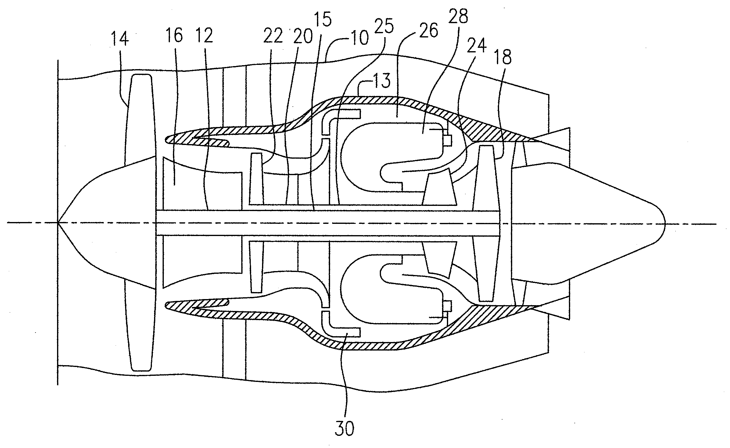
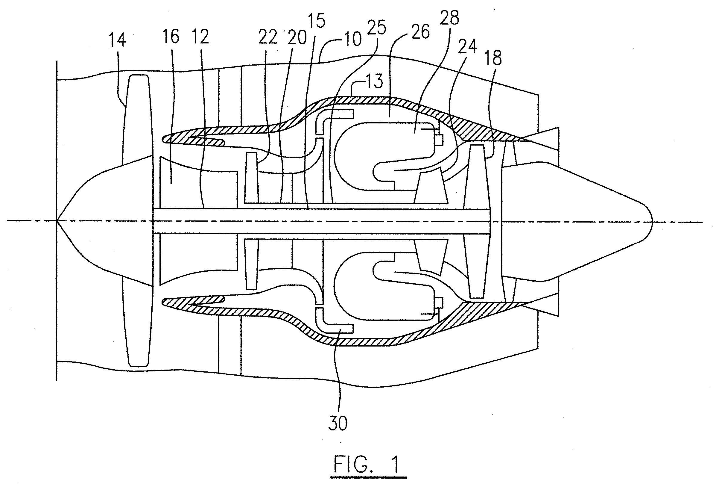
[0015]Referring to FIG. 1, a turbofan gas turbine engine incorporating an embodiment of the present invention is presented as an example of the application of the present invention, and includes a housing 10, a core casing 13, a low pressure spool assembly seen generally at 12 which includes a shaft 15 interconnecting a fan assembly 14, a low pressure compressor 16 and a low pressure turbine assembly 18, and a high pressure spool assembly seen generally at 20 which includes a shaft at 25 interconnecting a high pressure compressor assembly 22 and a high pressure turbine assembly 24. The core casing 13 surrounds the low and high pressure spool assemblies 12 and 20 in order to define a main fluid path (not indicated) therethrough. In the main fluid path there are provided a combustion section 26 having a combustor 28 therein. Pressurized air provided by the high pressure compressor assembly 22 through a diffuser 30 enters the combustion section 26 for combustion taking place in the com...


PUM


Abstract

An apparatus for adjusting a thrust load on a rotor assembly of a gas turbine engine includes an impeller rear cavity defined between a rear face of an impeller of the rotor assembly and a stationary wall spaced axially apart from the rear surface of the impeller. A pressurized air flow with a tangential velocity is introduced into the impeller rear cavity at a tip of the impeller to pressurize the cavity. Means are provided in the cavity for directly interfering with the tangential velocity of the pressurized air flow to affect an average static pressure of the pressurized air flow within the cavity in order to adjust the thrust load on the rotor assembly caused by the average static pressure in the cavity.

Description

TECHNICAL FIELD[0001]The invention relates generally to gas turbine engines, and more particularly to gas turbine engines having improved thrust bearing load control.BACKGROUND OF THE ART[0002]Gas turbine engines such as those used as aircraft turbojets or turbofans typically comprise a rotating fan, compressor and turbine that are axially mounted to one or more coaxial shafts for rotation about a central axis of the engine. The shafts are rotatably supported by at least two bearing assemblies and the front-most bearing assembly in the direction of fluid flow in the engine also prevents axial movement of the shaft within the engine case and is referred to as a “thrust bearing assembly”. Despite thrust bearing assemblies typically being machined to tight tolerances, a small amount of axial play in the thrust bearing assembly exists. This play is undesirable as it causes noise and vibration of the engine when the engine is in operation. Much of this play can be eliminated by exerting ...

Claims


Application Information

Patent Timeline
IPC IPC(8): F01D3/00F04D29/40F02C3/00
CPCF01D3/04
Inventor LEGARE, PIERRE-YVES
Owner PRATT & WHITNEY CANADA CORP
Why Eureka
Try Eureka