Tourbillon watch winder

a technology of tourbillon watch and winder, which is applied in the direction of electric winding, instruments, and horology, can solve the problems of original positional problem returning, inaccuracy imparted to the watch mechanism by the effects of gravity, etc., and achieve the effect of no significant inaccuracy

Inactive Publication Date: 2007-05-03
AGNOFF CHARLES
View PDF7 Cites 18 Cited by
  • Summary
  • Abstract
  • Description
  • Claims
  • Application Information

AI Technical Summary

Benefits of technology

[0009] Unlike prior art watch winders in which the watch carrier and watch are positioned at the same or a random orientation at the end of each winding cycle, the present watch winder achieving this desired tourbillon effect by stopping the watch carrier at the end of each cycle with the orientation of the watch carrier being at a predetermined number of degrees different from the orientation of the watch carrier at the end of the immediately preceding cycle. By initiating numerous winding cycles during a 24 hour period, the watch will not remain at any given orientation for any significant period. As a result, there is no significant inaccuracy resulting from gravitational effects.
[0018] More specifically, one kind of suitable watch winder may be comprised of a watch carrier and a rest to support and rotate the watch carrier for predetermined periods at selected times. The watch carrier is freely supported on the rest. The term “freely supported” as used herein means that the watch carrier is only secured to the rest by the weight of the watch carrier. As a result, the carrier can be quickly removed or replaced with another watch carrier, or reversed, i.e., turned end-to-end to reverse the direction of rotation of the carrier and any watch supported within the carrier.
[0027] As the cylinder rotates, the watch carried on the watch holder also rotates. The rotor, however, hangs downward and does not rotate. Therefore, the watch is wound due to the relative movement of the watch mechanism, in particular the watch spring, and the rotor. Rotation of the cylinder carries the detectable features sequentially past the sensor, which transmits a signal to the controller each time a feature is detected. When a predetermined number of signals have been received by the controller, the controller causes the circuit to open, stopping the cylinder with the last detected feature adjacent the sensor. The controller is programmed to open the circuit when a predetermined number of features different from the total number of features on the cylinder is sensed, thereby stopping the cylinder and the watch supported thereon at an orientation different from the orientation at the end of the immediately preceding cycle. Since the cylinder and watch are stopped at different predetermined locations after each cycle and since the watch winder is programmed to undergo several cycles, e.g., from about 500 to about 1300 cycles during a twenty-four hour period, the watch will not remain at any given orientation for a prolonged period. Therefore, the adverse effects of gravity are avoided and the advantages previously achievable only with a tourbillon mechanism are achieved.

Problems solved by technology

In either case when the watch is worn, the user's random and often rapid arm movements cause the rotor to swing back and forth inertially in both directions around the rotor axis, thereby winding the watch spring.
However, if the watch is not worn regularly, the user must wind the watch, either manually or with a watch winder, or the watch will stop.
One disadvantage of existing watch winders is the inaccuracy imparted to the watch mechanism by the effects of gravity.
However, with the advent of watchwinders, the original positional problem returns.

Method used


Image

  • Tourbillon watch winder
  • Tourbillon watch winder
  • Tourbillon watch winder

Examples


Embodiment Construction

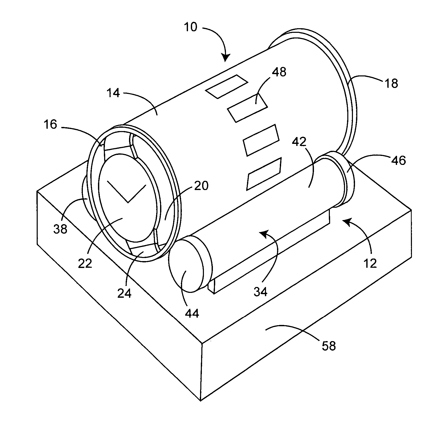
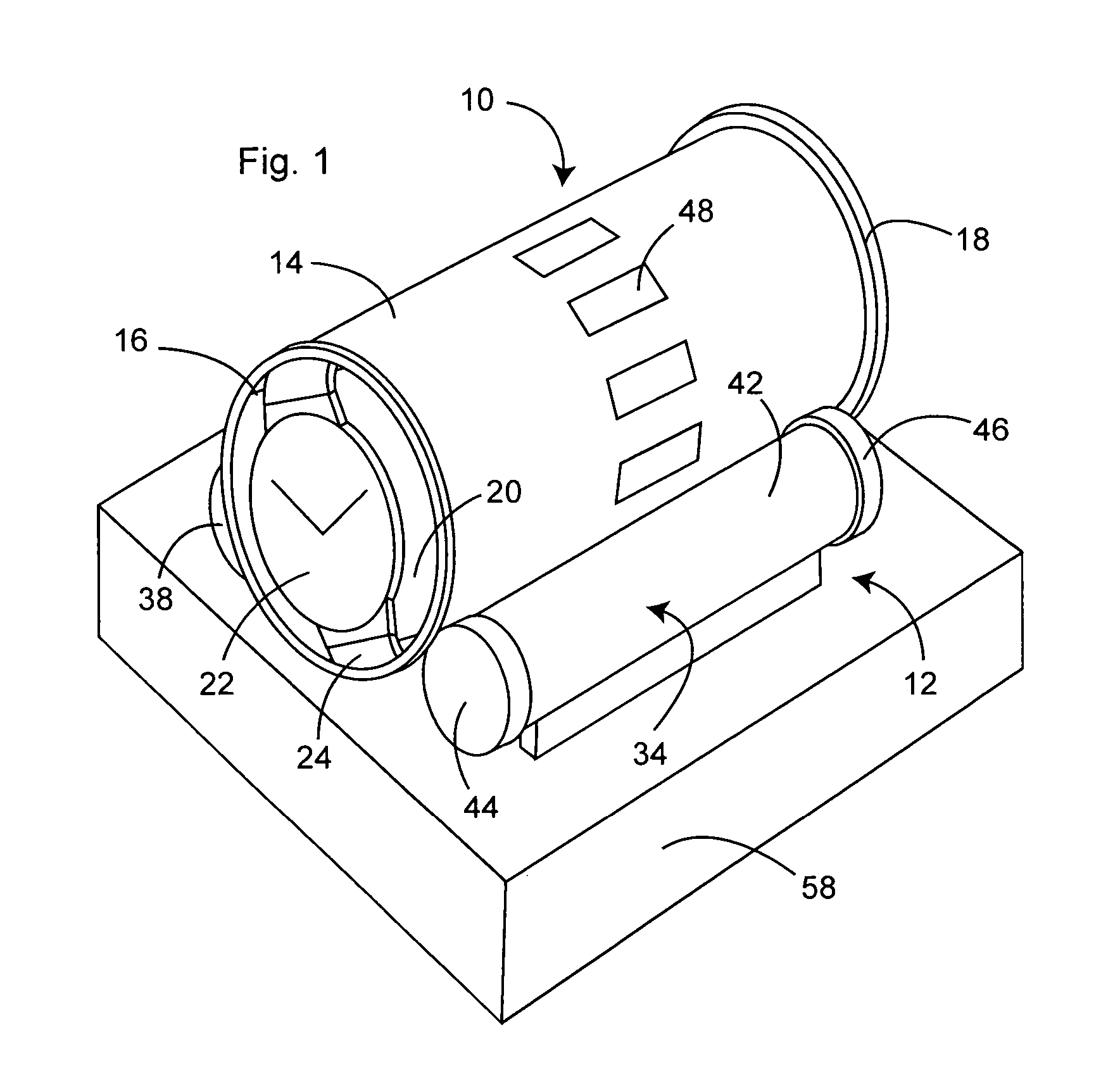
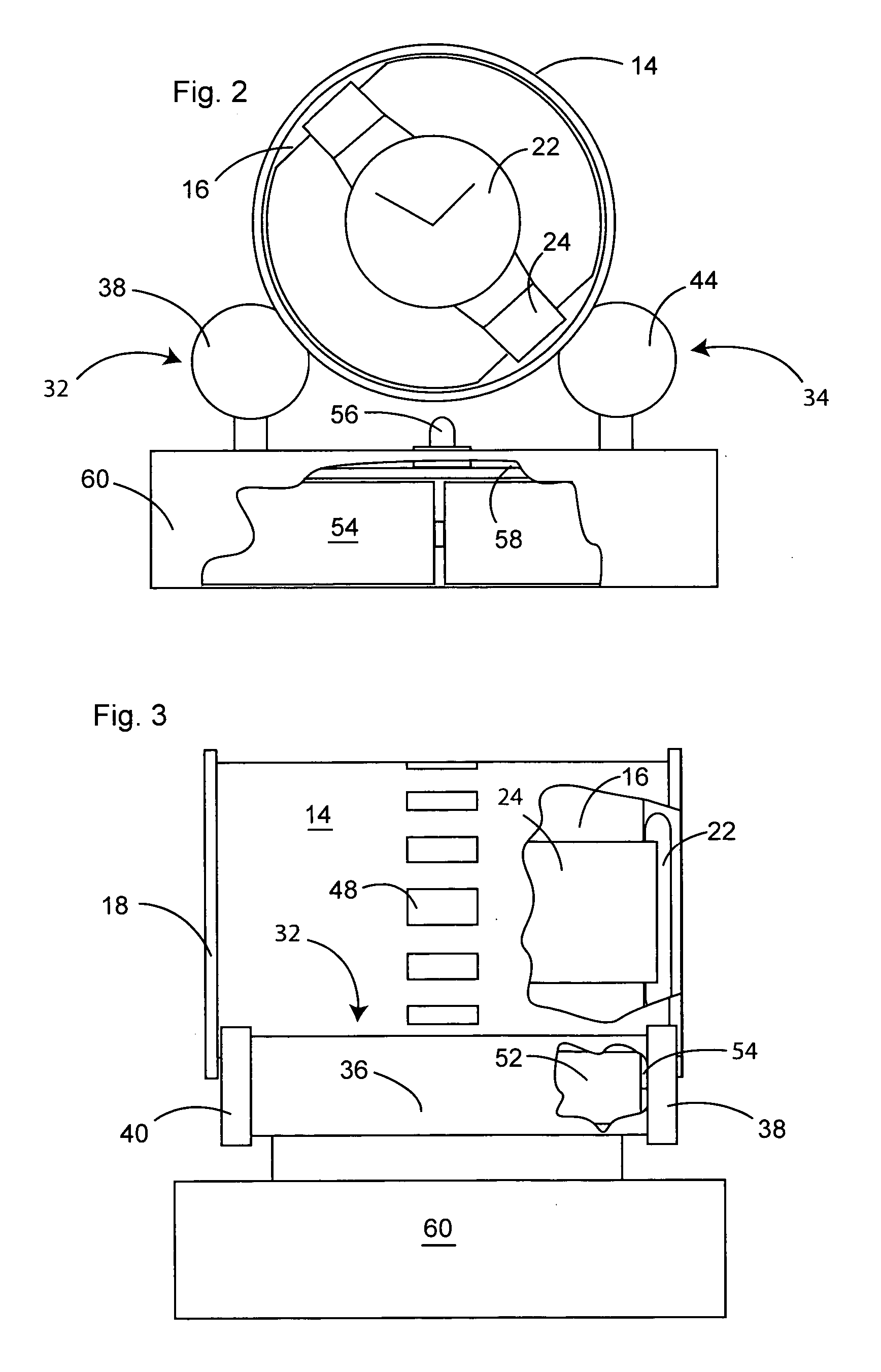
[0037] As best illustrated in FIGS. 1-3, a preferred embodiment of the watch winder of the present invention is comprised of a watch carrier, generally 10, and a rest, generally 12, to freely support watch carrier 10. Watch carrier 10 is comprised of horizontal cylinder 14 having a given diameter, a longitudinal axis, a continuous outer wall of a given length, an interior chamber defined by the inner wall of cylinder 14, and opposed ends, and watch holder 16 insertable into the interior chamber of cylinder 14. Cylinder 14 includes radial flanges 18 adjacent its ends.

[0038] Watch holder 16 includes watch-carrying face 20 perpendicular to the longitudinal axis of cylinder 14 so that watch 22 with watchband 24 can be mounted with the watch face and the plane of rotation of the rotor perpendicular to the longitudinal axis of cylinder 14. Holder 16 may be of various constructions so long as it is insertable into cylinder 14.

[0039] Rest 12 is comprised of first and second support sectio...


PUM


Abstract

A watch winder includes a watch carrier having a longitudinal axis, a continuous outer wall having a plurality of detectable features, and a watch holder to support the watch relative to the longitudinal axis so that the watch rotates upon rotation of the carrier about the longitudinal axis; a drive means within a circuit including a controller to control the rotation of the watch carrier through successive winding cycles; and a sensor to detect the position of the detectable features, the controller stopping the carrier at the end of each cycle in response to detection of a given number of detectable features by the sensor, the feature detected at the end of each cycle being different from the feature detected by the sensor at the end of the immediately preceding cycle.

Description

BACKGROUND OF THE INVENTION [0001] (1) Field of the Invention [0002] The present invention relates generally to automatic watch winders for winding self-winding watches, and in particular to watch winders that end each winding cycle with the orientation of the watch carrier, and the watch supported thereon, at a predetermined number of degrees different from the orientation of the watch carrier at the end of the immediately preceding cycle, thereby imparting to the watch the accuracy and advantages of a tourbillon mechanism. [0003] (2) Description of the Prior Art [0004] The winding mechanism of a self-winding watch is comprised of a bearing mounted pendulum or rotor that is connected through a gear reduction system to the mainspring of the watch. Generally, the rotor can rotate 360° in either direction. However, there are also so-called “hammer” shaped rotors in older self-winding watches that have a limited travel of 150° to 220° rotation. In either case when the watch is worn, th...

Claims


Application Information

Patent Timeline
Patent Type & Authority Applications(United States)
IPC IPC(8): G04B3/00
CPCG04B3/006G04C1/00G04C1/04G04D7/009
Inventor AGNOFF, CHARLES
Owner AGNOFF CHARLES
Why Eureka
Try Eureka