Bicycle hub

Inactive Publication Date: 2007-05-03
SHIMANO INC
View PDF9 Cites 3 Cited by
  • Summary
  • Abstract
  • Description
  • Claims
  • Application Information

AI Technical Summary

Benefits of technology

[0010] One object of the present invention is to provide to a hub with an inner tubular structure th

Problems solved by technology

However, since there is the clearance between the outer ring and the hub axle in at an axial inner position of the bearing, the grease filled within the bearing occasionally

Method used


Image

  • Bicycle hub
  • Bicycle hub
  • Bicycle hub

Examples


Example

Second Embodiment

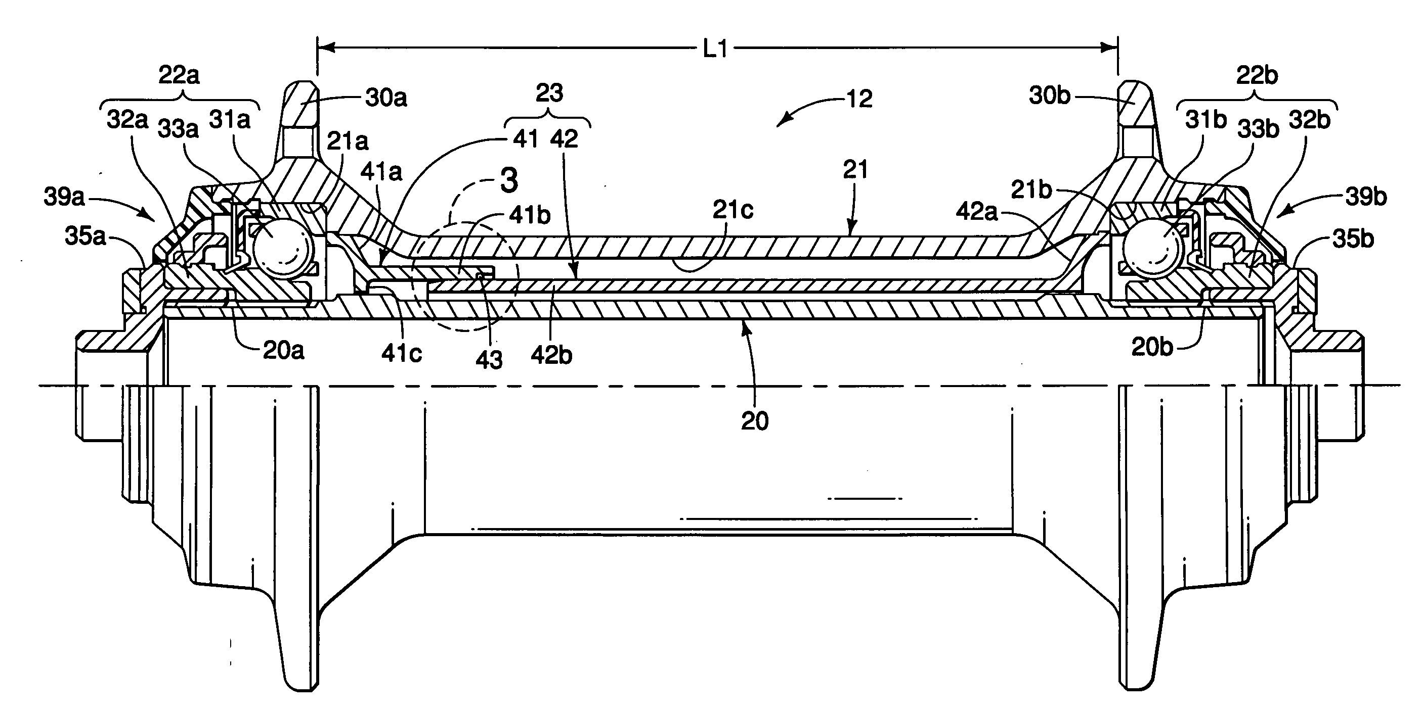
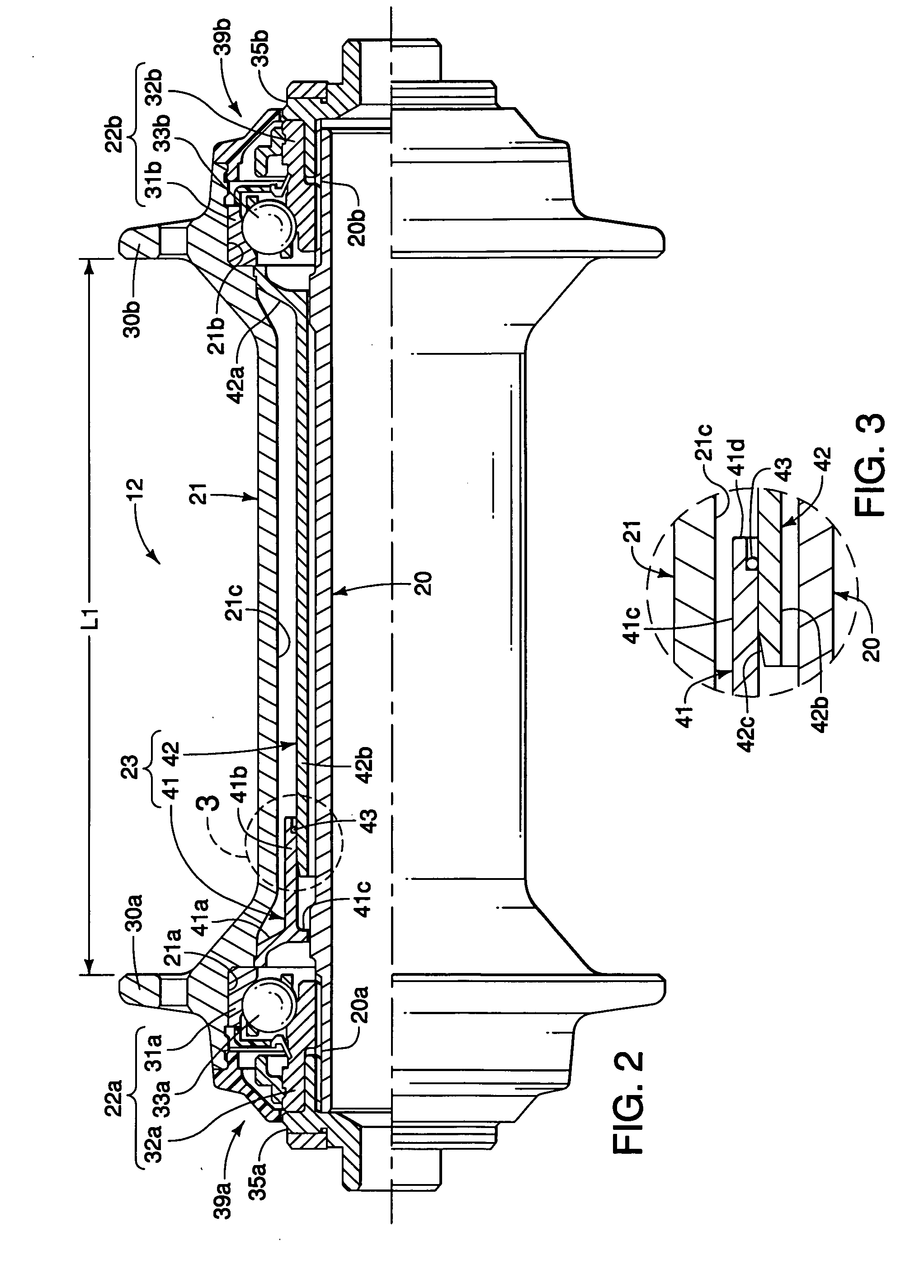
[0042] Referring now to FIGS. 7-10, a modified front hub 12′ with a modified inner tubular structure 23′ for substantially preventing grease from flowing out from the bearings 22a and 22b toward the inner axial direction is illustrated in accordance with a second embodiment. Basically, the modified front hub 12′ is identical to the front hub 12, except for the modified inner tubular structure 23′. Thus, the identical parts of the front hubs 12 and 12′ will be given the same reference numerals.

[0043] In this embodiment, the inner tubular structure 23′ basically includes a first or left inner tube 41′ (FIG. 9), a second or right inner tube 42′ (FIG. 10), and a sealing element 43′ (FIG. 8). The left and right inner tubes 41′ and 42′ are telescopically arranged so that they can be used with hubs having different axial lengths between the left and right bearings 22a and 22b. For example, the inner tubular structure 23′ can be used in the front hub 112 of FIG. 4.

[0044]...


PUM


Abstract

A bicycle hub is provided that comprises a hub axle, a hub body rotatably mounted on the hub axle by a pair of bearings. The bicycle hub also has an inner tubular structure including a pair of inner tubes. One of the inner tubes is fixedly secured relative to a first body end adjacent to a first bearing, while the other inner tube is fixedly secured relative to the second body end adjacent to the second bearing. The inner tubes have inner free end portions that are telescopically arranged so that the inner tubes can be used with several different has that have different axial widths.

Description

BACKGROUND OF THE INVENTION [0001] 1. Field of the Invention [0002] The present invention generally relates to a bicycle hub of a bicycle wheel that is mounted to a bicycle frame. More specifically, the present invention relates to a bicycle hub with an inner tubular structure for substantially preventing the bearing grease from leaking towards the center of the hub. [0003] 2. Background Information [0004] Bicycling is becoming an increasingly more popular form of recreation as well as a means of transportation. Moreover, bicycling has become a very popular competitive sport for both amateurs and professionals. Whether the bicycle is used for recreation, transportation or competition, the bicycle industry is constantly improving the various components of the bicycle as well. One component that has been extensively redesigned is the hub of the bicycle. [0005] Generally, bicycle hubs have a hub shaft or axle mounted in a non-rotatable manner to a rear part of the bicycle frame and a h...

Claims


Application Information

Patent Timeline
IPC IPC(8): F16C13/00
CPCB60B27/0005B60B27/0073B60B27/023
Inventor KANEHISA, TAKANORINISHIMURA, ATSUHIRO
Owner SHIMANO INC
Why Eureka
Try Eureka