Switch device

Inactive Publication Date: 2009-07-30
KK TOKAI RIKA DENKI SEISAKUSHO
View PDF3 Cites 67 Cited by
  • Summary
  • Abstract
  • Description
  • Claims
  • Application Information

AI Technical Summary

Benefits of technology

[0014]According to the invention, it is possible to prevent grease from reaching a fixed contact portion, thereby preventing ge

Problems solved by technology

However, according to the conventional switch device, since a fixed contact portion corresponding to the push switch (a movable pressure contact portion) and a fixed contact portion corresponding to the rotary switch (a movable sliding contact portion) are provided on a mutual circuit board, a portion of the grease moves

Method used


Image

  • Switch device
  • Switch device
  • Switch device

Examples


embodiment

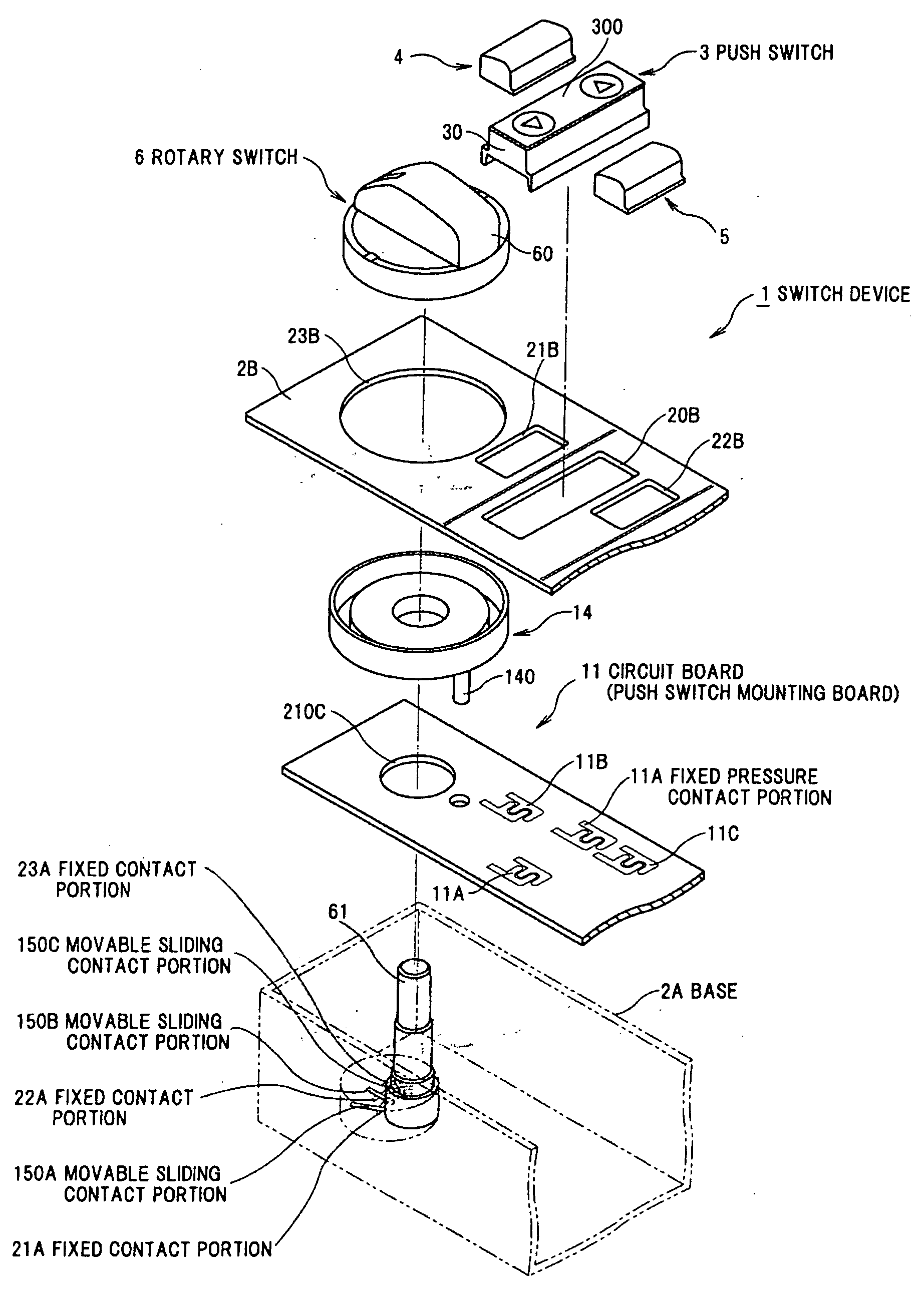
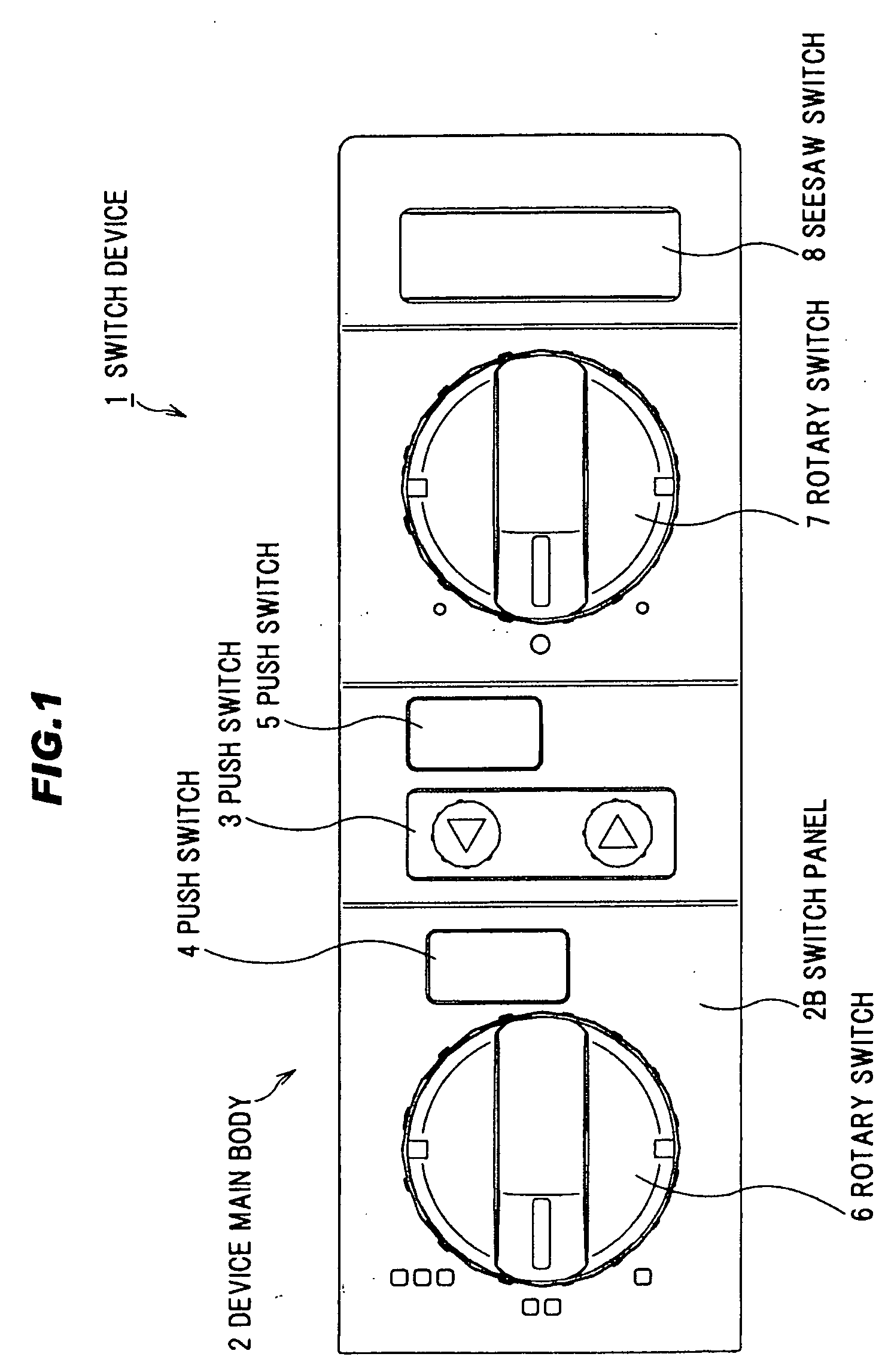
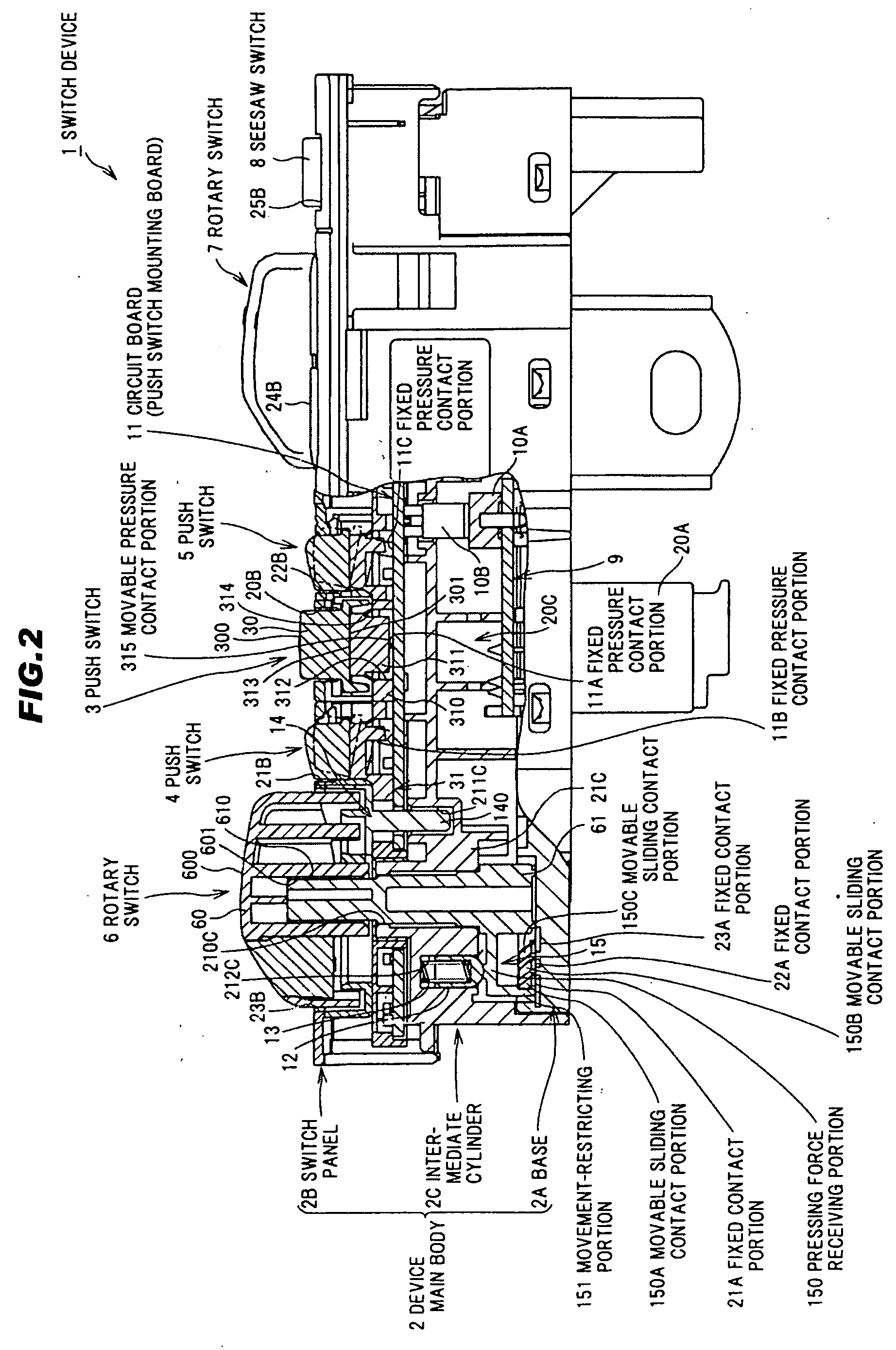
[0019]FIG. 1 is an explanatory plane view showing a total structure of a switch device in a preferred embodiment of the invention. FIG. 2 is an explanatory cross sectional view showing a total structure of a switch device in the embodiment of the invention. FIG. 3 is an explanatory exploded perspective view showing a total structure of a switch device in the embodiment of the invention.

Total Structure of a Switch Device

[0020]In FIGS. 1 to 3, a switch device 1 is composed of a device main body 2, push switches 3, 4 and 5 as a pressure-operated switch, and rotary switches 6 and 7 (and a seesaw switch 8) as a slide-operated switch.

Structure of the Device Main Body 2

[0021]As shown in FIG. 2, the device main body 2 is composed of a base 2A forming a bottom portion of a case, a switch panel 2B forming a ceiling portion of the case by facing the base 2A and an intermediate cylinder 2C interposed between the switch panel 2B and the base 2A. The device main body 2 is composed of, e.g., a sea...


PUM


Abstract

A switch device, includes a device main body incorporating a fixed pressure contact portion and includes a fixed sliding contact portion that forms a circuit together with the fixed pressure contact portion, and at least one pair of switches supported on the device main body, each switch comprising an operating knob. One switch of the at least one pair of switches includes a pressure-operated switch includes a movable pressure contact portion corresponding to the fixed pressure contact portion, and another switch includes a slide-operated switch includes a movable sliding contact portion corresponding to the fixed sliding contact portion.

Description

[0001]The present application is based on Japanese Patent Application No. 2008-017511 filed on Jan. 29, 2008, the entire contents of which are incorporated herein by reference.BACKGROUND OF THE INVENTION[0002]1. Field of the Invention[0003]The present invention relates to a switch device, in more particular, to a switch device provided with a pressure-operated switch and a slide-operated switch.[0004]2. Related Art[0005]As a conventional switch device, JP-A-10-197035 discloses a switch device provided with a case having a display panel and various types of switches having an operating knob exposed on the display panel of the case.Inside the case, the above-mentioned display panel is arranged on a switch operating side, and a circuit board mounting various types of switches as well as a control portion is housed.The various types of switches are composed of a push switch and a rotary switch, etc., each operably supported on the circuit board and connected to a drive portion via a swi...

Claims


Application Information

Patent Timeline
IPC IPC(8): H01H13/76
CPCH01H13/807H01H2201/038H01H2203/026H01H2231/026H01H2221/014H01H2221/018H01H2225/03H01H2221/01
Inventor WATANABE, RYOJI
Owner KK TOKAI RIKA DENKI SEISAKUSHO
Why Eureka
Try Eureka