Air-refrigerant cooling apparatus

Inactive Publication Date: 2007-05-10
MITSUBISHI HEAVY IND LTD +1
View PDF3 Cites 8 Cited by
  • Summary
  • Abstract
  • Description
  • Claims
  • Application Information

AI Technical Summary

Benefits of technology

[0019] According to the present invention, an air-refrigerant co

Problems solved by technology

Accordingly, defrosting is an important iss

Method used


Image

  • Air-refrigerant cooling apparatus
  • Air-refrigerant cooling apparatus
  • Air-refrigerant cooling apparatus

Examples


Example

[0025] A best mode for carrying out the present invention will be described hereinafter in detail with reference to the drawings.

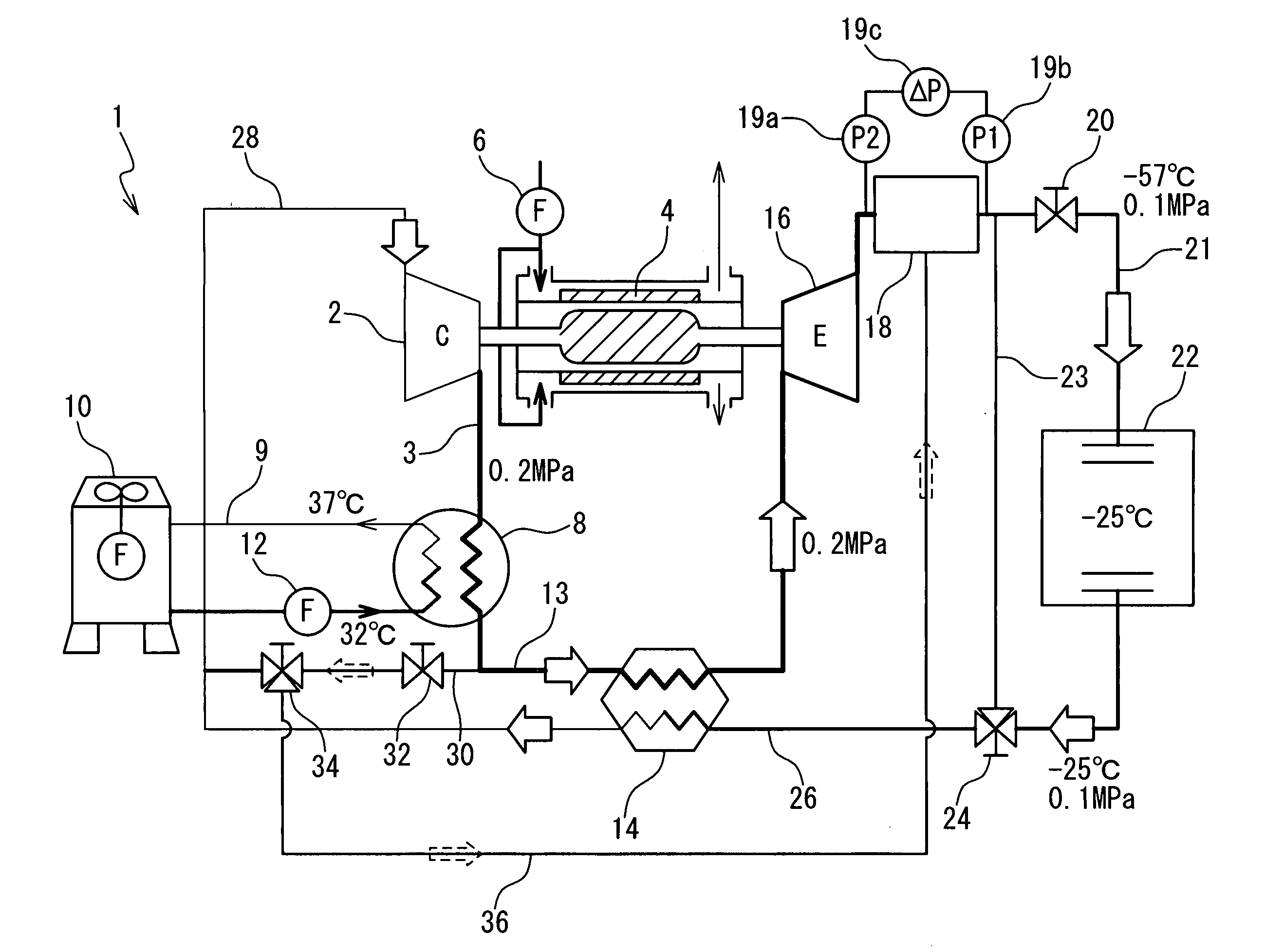
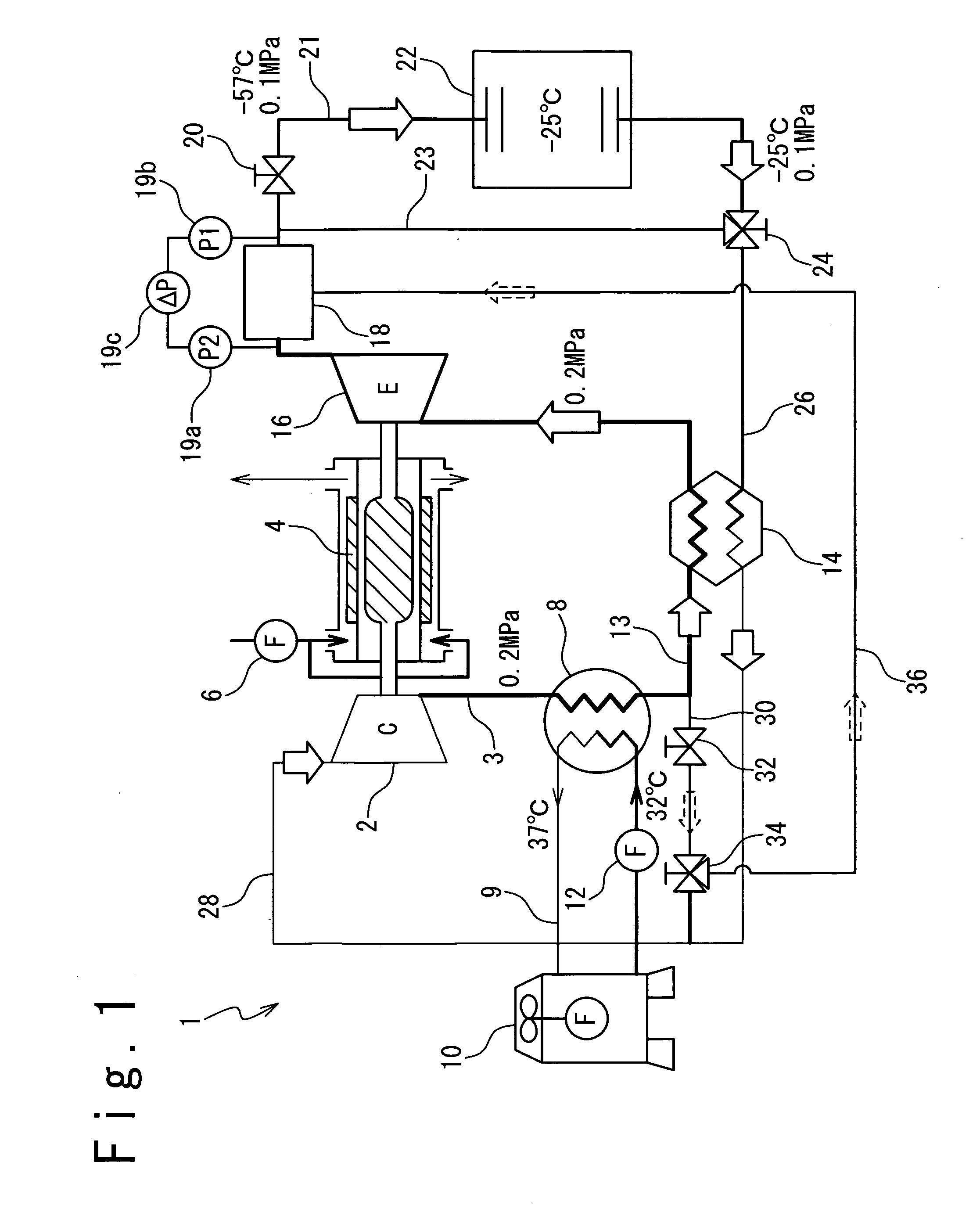
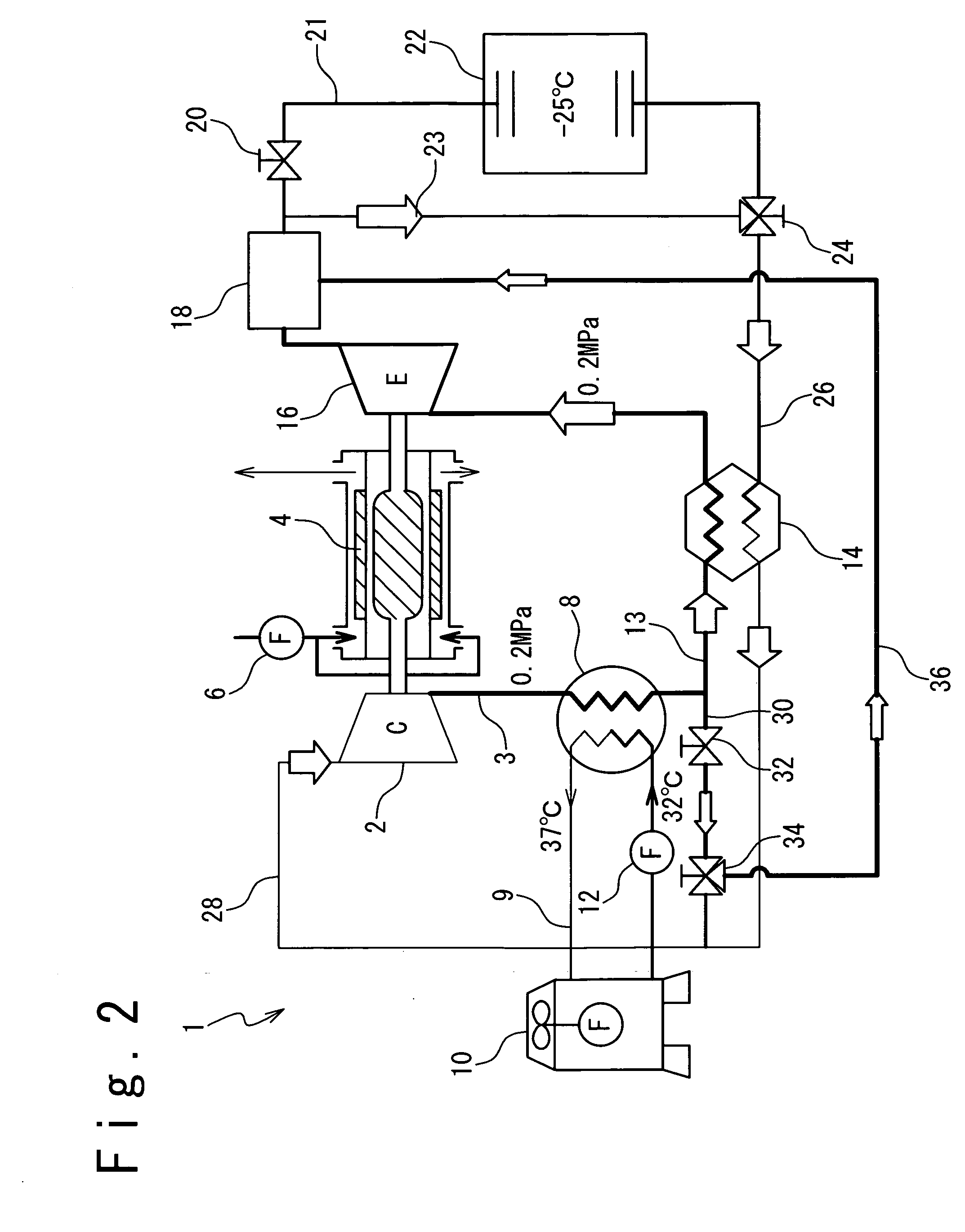
[0026] Referring to FIG. 1, shown is an exemplary configuration of an air-refrigerant cooling apparatus according to one embodiment of the present invention. The term “cooling apparatus” is intended to include a freezing apparatus, a refrigerating apparatus, and an air-conditioning cooling apparatus, which are different in temperature and pressure of the system; this also applies to the cooled warehouse. In the following description, the term “warehouse” refers to a space to be cooled by the cooling apparatus. The air-refrigerant cooling apparatus 1 includes a compressor 2. The compressor 2 is driven by a motor 4. The motor 4 is cooled by a cooling fan 6.

[0027] A pipe 28 is connected to the inlet of the compressor 2. The outlet of the compressor 2 is connected to a water-cooled heat exchanger 8 through an air pipe 3. The water-cooled heat exchanger 8 inc...


PUM


Abstract

The present invention provides a technique for rapidly removing frost accumulated in air-refrigerant cooling apparatuses. An air-refrigerant cooling apparatus in accordance with the present invention includes a bypass line for directly supplying a defroster with refrigerant air having an increased temperature from a compressor, avoiding temperature drop by a heat exchanger and an expansion turbine. Moisture of the frost melted in the defroster is externally exhausted by a fan.

Description

TECHNICAL FIELD [0001] The present invention relates to cooling apparatuses using air as refrigerant. BACKGROUND ART [0002] Cooling apparatuses using air as refrigerant have been recently developed as alternatives of conventional cooling apparatuses using chlorofluorocarbon as refrigerant. [0003] For example, Japanese Laid Open Patent Publication No. H05-106944 discloses a refrigerating apparatus composed of a compressor, a condenser including a blowing fan, a pressure reducing unit, and an evaporator including a blowing fan, which are sequentially connected. This refrigerating apparatus includes a first switching valve that is provided downstream or upstream of the condenser and that opens and closes a refrigerant channel of the condenser, a first bypass circuit that bypasses this first switching valve and the condenser, a second switching valve that is provided in this first bypass circuit and that opens and closes the first bypass circuit, a second bypass circuit that bypasses th...

Claims


Application Information

Patent Timeline
IPC IPC(8): F25D21/00F25D9/00
CPCF25B9/004
Inventor OKUDA, SEIICHIMITSUHASHI, MASATO
Owner MITSUBISHI HEAVY IND LTD
Why Eureka
Try Eureka