Heat pump

Inactive Publication Date: 2006-09-12
SANYO ELECTRIC CO LTD
View PDF22 Cites 14 Cited by
  • Summary
  • Abstract
  • Description
  • Claims
  • Application Information

AI Technical Summary

Benefits of technology

[0022]Furthermore, because the refrigerant density is substantially constant and the volume of the refrigerating cycle is constant, the amount of the refrigerant being circulated is constant and thus the variation of

Problems solved by technology

There is a problem in that when the temperature of water being supplied is varied and the temperature at the exit of the gas cooler is varied, the density of the refrigerant is varied.
When some difference occurs in the optimum refrigerant amount, if refrigerant is filled so as to support a driving operation which requires a large optimum refrigerant amount, there would occur various problems such as surplus refrigerant occurring in a driving operation requiring a small optimum refrigerant amount and, thus, a receiver tank or the like for temporarily stocking the surplus refrigerant is needed, that the control for achieving the optimum refrigerant amount is complicated, etc.
However, for example, when the hot gas defrosting operation is carried out under a conditio

Method used


Image

  • Heat pump
  • Heat pump
  • Heat pump

Examples


Example

[0028]Embodiments of the present invention will be described with reference to the drawings.

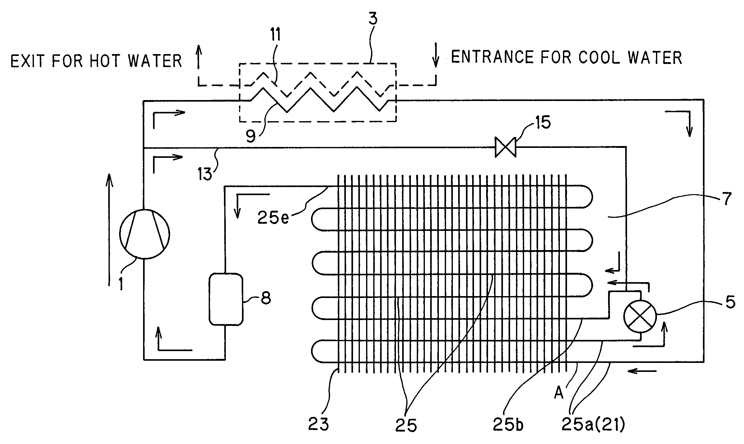
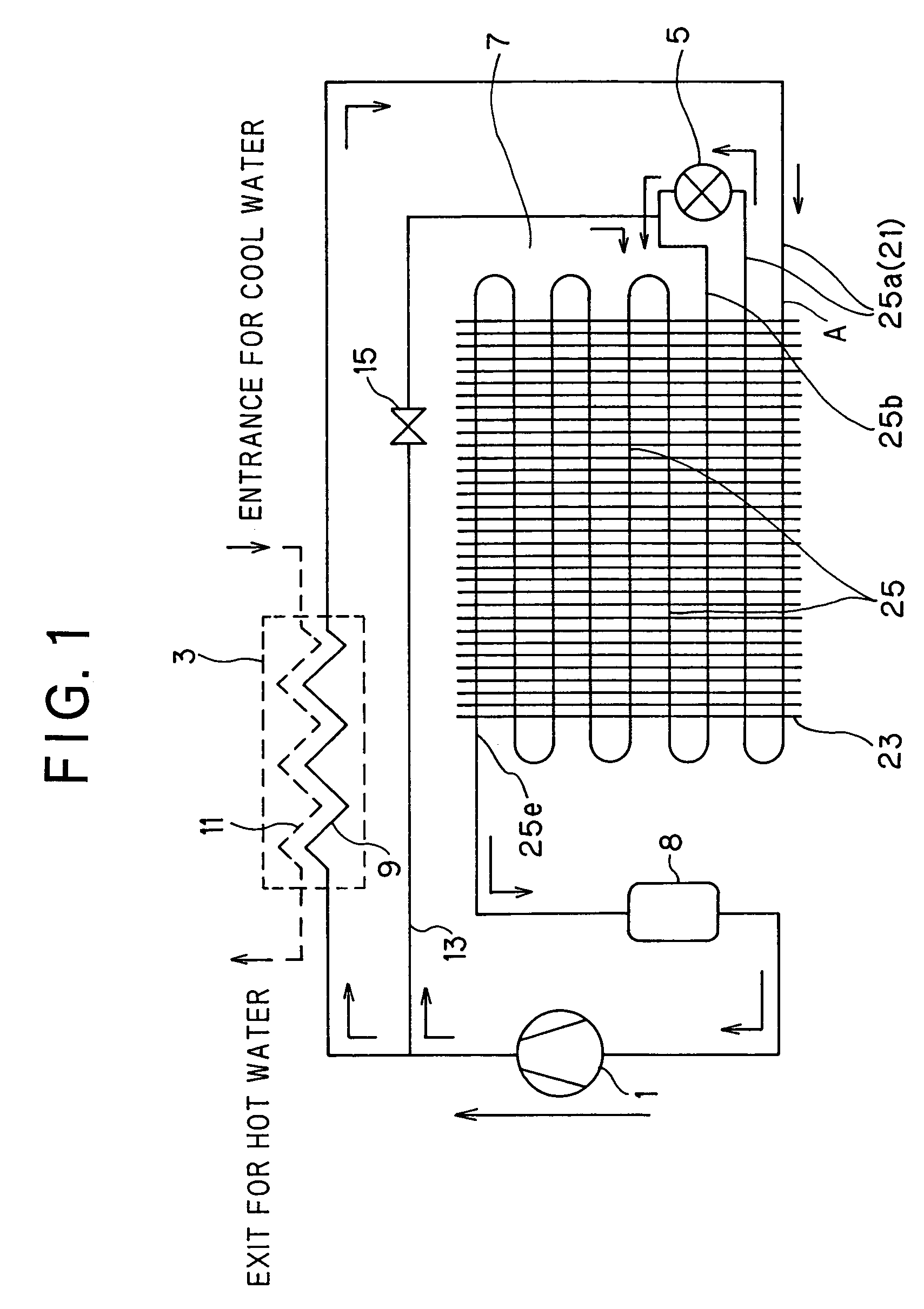
[0029]In FIG. 1, reference numeral 1 represents a compressor, and a gas cooler 3, a pressure reducing device (expansion valve) 5, an evaporator 7 comprising a fin tube type air heat-source type heat exchanger, and an accumulator 8 are connected in this order to the compressor 1 through a refrigerant pipe, as indicated by a solid line to thereby constitute a refrigerating cycle.

[0030]CO2 refrigerant is filled and used in the refrigerating cycle. The ozone depletion coefficient of CO2 refrigerant is equal to 0, and the global warming potential thereof is equal to 1. Therefore, this refrigerant has a small load on the environment, has no toxicity and no inflammability, and is safe and low in cost.

[0031]The gas coil 3 comprises a refrigerant coil 9 indicated by a solid line through which CO2 refrigerant flows, and a water coil 11 indicated by a broken line through which water flows, and the water...


PUM


Abstract

A heat pump apparatus that having a refrigerating cycle including a compressor, a gas cooler, a pressure reducing device and an evaporator and is designed so that water can be heated by the gas cooler. A refrigerant such as CO2 or the like working in a supercritical area is filled and used at a high-pressure side in the refrigerating cycle and a radiator is equipped between the exit of the gas cooler and the pressure reducing device. The refrigerant temperature at the exit of the radiator is kept at a substantially fixed temperature irrespective of the temperature of hot water to the gas cooler.

Description

BACKGROUND OF THE INVENTION[0001]1. Field of the Invention[0002]The present invention relates to a heat pump apparatus, and more particularly to a heat pump apparatus which can enhance the defrosting efficiency of an evaporator and suppress variation of the optimum refrigerant filing amount when the temperature of water being supplied is varied in a heat pump type hot water supply apparatus designed so as to supply hot water heated by a gas cooler.[0003]2. Description of the Related Art[0004]There is known a heat pump type hot water supply apparatus that generally has a refrigerating cycle including a compressor, a gas cooler, a pressure reducing device and an evaporator and is designed to supply hot water heated by the gas cooler.[0005]For example, when CO2 refrigerant is used as a refrigerant in a refrigerating cycle in this type of apparatus, it is expected that a high coefficient of performance (COP) can be achieved in a heating process having a large water-temperature rise-up r...

Claims


Application Information

Patent Timeline
IPC IPC(8): F25D21/00F25B6/04F25B9/00F25B29/00F25B30/02F25B39/02F25B41/04F25B47/00F25B47/02F28D1/04F28D1/047
CPCF25B6/04F25B9/008F25B29/003F25B30/02F25B39/02F25B41/04F28D1/0477F28D1/0443F25B47/006F25B47/022F25B2309/061F25B2339/047F25B2500/01Y02A40/963F25B41/20F25B1/00
Inventor KUWABARA, OSAMUMUKAIYAMA, HIROSHIKOBAYASHI, MASAHIROKAMIMURA, ICHIROIZAKI, HIROKAZUISHIHARA, TOSHIKAZU
Owner SANYO ELECTRIC CO LTD
Why Eureka
Try Eureka