[0003] The present invention is directed to a power tool with a removable
power supply unit on the device side for supplying electrical power, with at least one indirectly operable switch for switching a drive
machine on and off.
[0004] It is provided that a decoupling device for decoupling the switch and a switching means that actuates the switch at least indirectly are provided. The decoupling device, in particular, is configured and / or designed accordingly. Switches and switching means can be set or actuated independently of each other.
[0005] The decoupling device is preferably provided to forcibly turn off the switch when the
power supply unit is removed and the switching means are locked in an “on” position, in which the switch can be switched on during normal operation. The decoupling device preferably includes at least one spring element. If the switching means are operatively connected with the spring element that causes the switch to turn on when the power supply unit is removed and the switching means are in the “on” position, simple and reliable handling is made possible. The normal operating state can be restored via a forcible release of the switching means from the “on” position. The power tool can be effectively prevented from accidentally starting up when the power supply unit is connected. The power supply unit is preferably a rechargeable-battery block or a battery block. The
operational reliability of a power tool with a lockable switching means is increased. The present invention is particularly suited for power tools with which the switching means is lockable in the “on” position during operation.
[0006] An additional level of protection is achieved when at least one blocking means for blocking a
coupling of the power supply unit when the switching means are in the “on” position and the switch is turned off. Maloperation is reliably prevented. The power supply unit cannot supply the switch with
electric power as long as the blocking means are in the blocked position. The operator must first move the switching means into an “off” position before the power supply unit can be completely reinserted in the power tool and the switch can be turned on with the switching means.
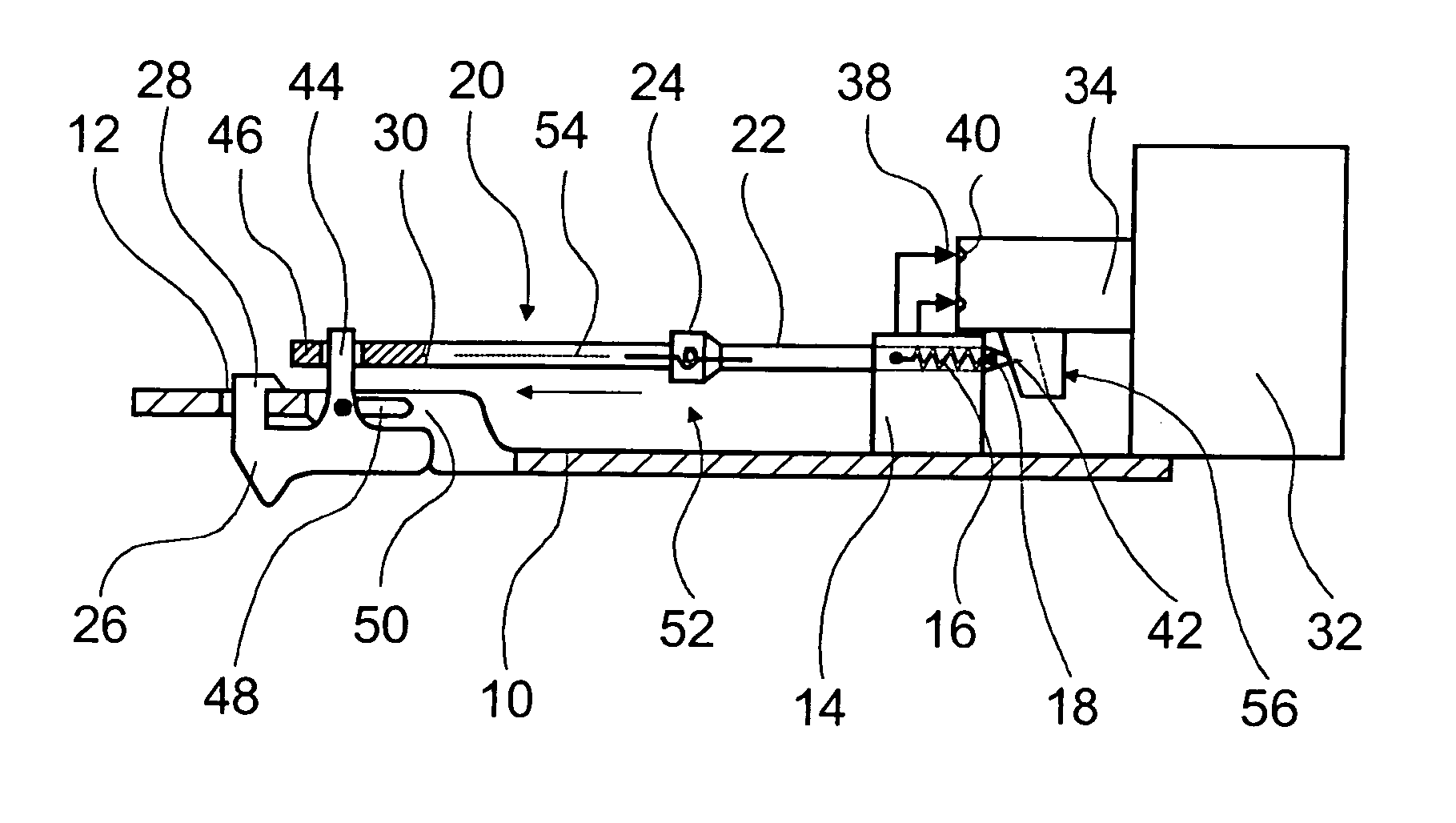
[0007] If an actuating device is located between the switching means and the switch that includes at least a portion of the decoupling device, it can actuate the switch on a case-by-case basis or block attachment of the power supply unit without requiring any additional components. The
system has a compact design and can be reliably operated. It is particularly advantageous when the actuating device includes at least one blocking means. Particularly
safe handling is made possible.
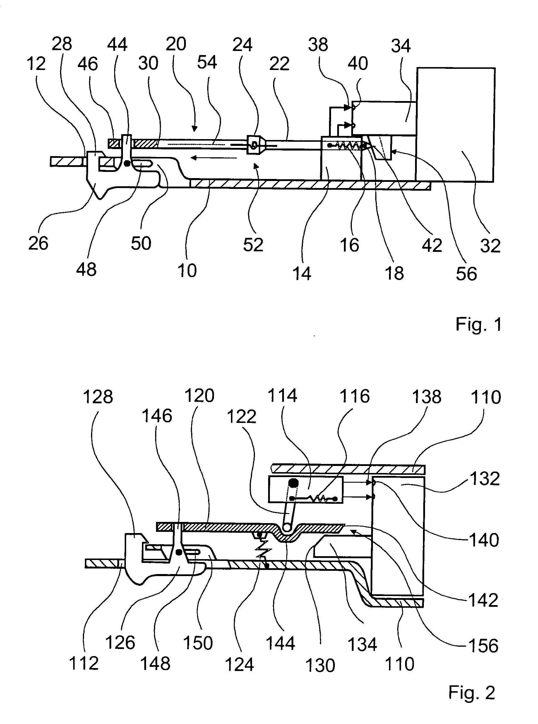
[0010] If the neck has a projection that is operatively connected with the actuating device, rotation of the actuating device can be easily enabled when the power supply unit is removed by the fact that, e.g., the projection slides over a lever and displaces it.
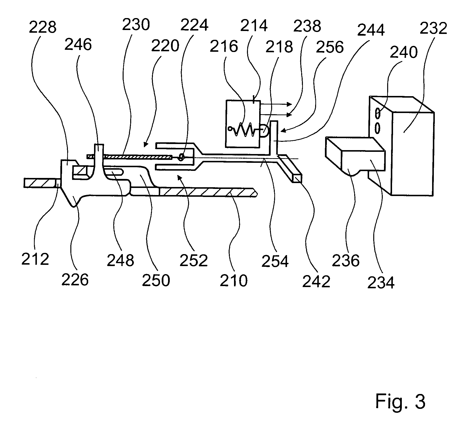
[0009] If the actuating device according to a first and third exemplary embodiment has a multi-position flexible
coupling, the spring element serving to rotate a first leg of the actuating device relative to a second leg that actuates the switch, the actuating device can be disengaged from the switch via rotation of the second leg. The actuating device can be detached from a pushbutton of the switch by rotating it while, when rotated in the reverse direction, the second leg impacts the pushbutton and is unable to engage with it until the switching element is moved into the “off” position and, to turn it on in normal operation, back to the “on” position. As an alternative, the actuating device is connected with a tension spring that disengages the actuating device and keeps it disengaged until the switching means are moved into the “off” position. To turn on the power tool, the switching means are moved back into the “on” position.
[0009] If the actuating device according to a first and third exemplary embodiment has a multi-position flexible coupling, the spring element serving to rotate a first leg of the actuating device relative to a second leg that actuates the switch, the actuating device can be disengaged from the switch via rotation of the second leg. The actuating device can be detached from a pushbutton of the switch by rotating it while, when rotated in the reverse direction, the second leg impacts the pushbutton and is unable to engage with it until the switching element is moved into the “off” position and, to turn it on in normal operation, back to the “on” position. As an alternative, the actuating device is connected with a tension spring that disengages the actuating device and keeps it disengaged until the switching means are moved into the “off” position. To turn on the power tool, the switching means are moved back into the “on” position.

