Methods and apparatus for fastening panels

a technology of fastening panels and methods, applied in the directions of snap fasteners, buckles, transportation and packaging, etc., can solve the problem of not using additional structural footprints

Inactive Publication Date: 2007-05-17
FAURECIA INTERIOR SYST
View PDF15 Cites 62 Cited by
  • Summary
  • Abstract
  • Description
  • Claims
  • Application Information

AI Technical Summary

Benefits of technology

[0017] The apparatus may further include at least one guide rib having at least a portion of a surface sloping toward the engagement plate to guide the head and shaft of the mating fastener into the aperture. For example, the at least one guide rib may include a respective guide rib disposed on opposite sides of the aperture, each guide rib having at least a portion of a surface sloping toward the engagement plate to guide the head and shaft of the mating fastener into the aperture. The guide rib(s) prevent the head from moving downward through the aperture and placing excessive pressure the clip (which might damage the clip and other structures).
[0018] In accordance with one or more aspects of the present invention, a method for coupling a panel to a frame includes: coupling an engagement plate substantially parallel to the panel, the engagement plate having an aperture extending therethrough which is oriented transversely to the panel, and a slot extending from a leading edge of the engagement plate to the aperture, the slot including inwardly directed side surfaces operable to guide a head and shaft of a mating fastener into the aperture; providing a clip having a pivotable arm extending from a first end at least partially under the aperture and at least toward the leading edge of the engagement plate to a second end; slideably receiving the head and shaft of the mating fastener into the aperture; and preventing the head and shaft of the mating fastener from sliding out of the aperture through the slot using the clip in tension.

Problems solved by technology

Thus, additional structural footprint need not be employed to accommodate a clip extending from the opposite direction.

Method used


Image

  • Methods and apparatus for fastening panels
  • Methods and apparatus for fastening panels
  • Methods and apparatus for fastening panels

Examples


Embodiment Construction

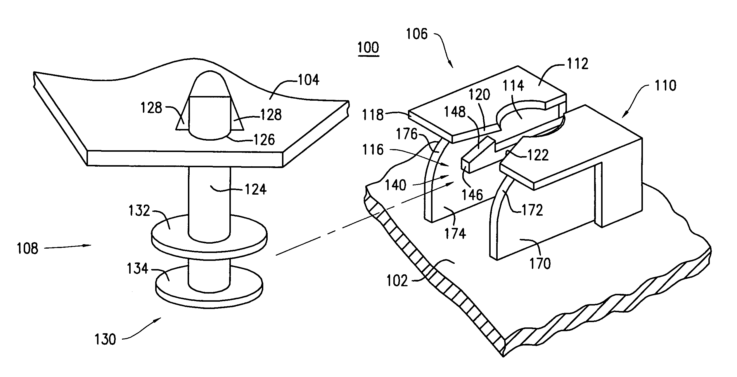
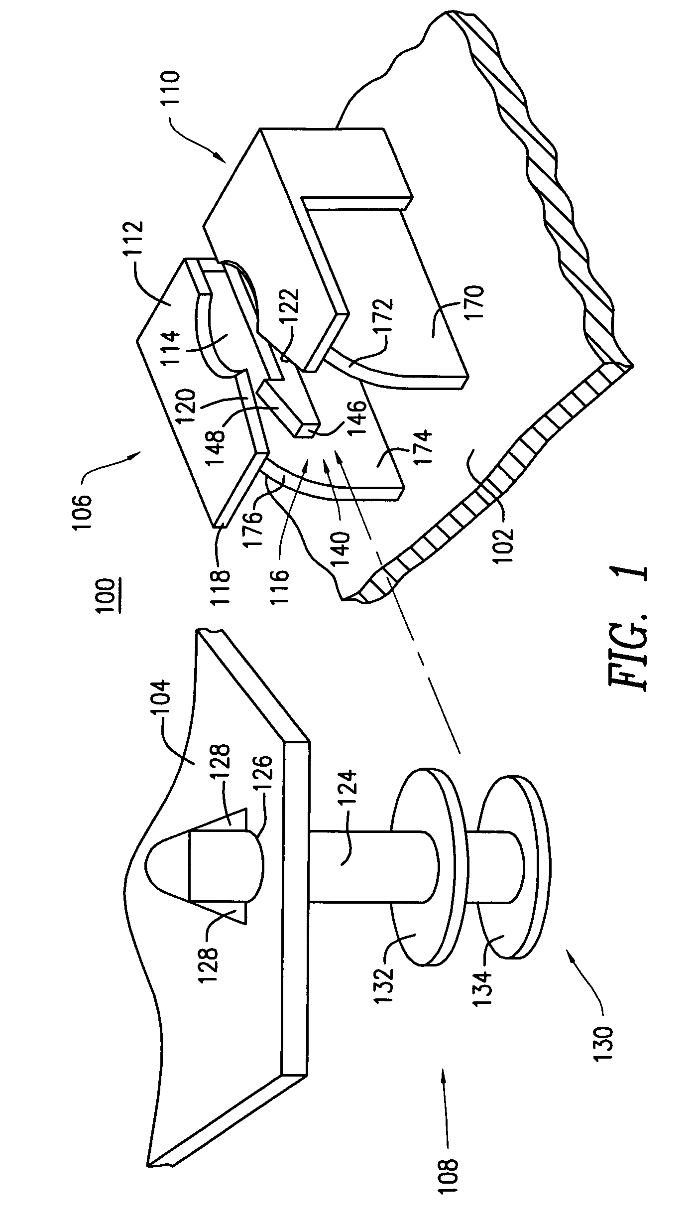
[0026] With reference to the drawings, wherein like numerals indicate like elements, there is shown in FIG. 1 a perspective view of a fastening system 100 for connecting a panel 102 to a frame 104 in accordance with one or more embodiments of the present invention. It will be appreciated by those skilled in the art that the panel 102 and frame 104 may be employed in any number of different mechanical contexts. By way of example, and not by limitation, the panel 102 may be a door trim panel 102 for the interior of an automobile and the frame 104 may be the door module 104 of the automobile to which the panel 102 is to be secured. The door module 104 preferably represents one or more structural elements of the door of a vehicle and the door trim panel 102 represents an aesthetically pleasing panel that covers the less aesthetically pleasing components of the door module 104. The door trim panel 102 is preferably coupled to the door module 104 by way of one or more fastening systems 10...


PUM


Abstract

An apparatus for coupling a panel to a frame includes: a support plate coupled to the panel; an engagement plate extending transversely from the support plate and having an aperture extending therethrough; and a clip having a pivotable arm extending from the support plate at a first end, and at least partially under the aperture to a second end, wherein the plate, aperture and clip are sized and shaped to slideably receive a head and shaft of a mating fastener, coupled to the frame, toward the support plate such that the second end of the pivotable arm engages the head when the shaft is fully received in the aperture.

Description

BACKGROUND OF THE INVENTION [0001] The present invention relates to methods and apparatus for fastening panels together, such as for securing a door trim panel to a door module of a vehicle. [0002] Door trim panels are employed as interior components on automotive vehicles. One of the purposes of such interior trim panels is to present an aesthetically pleasing appearance. Door trim panels are typically mounted to structural support members on the door module. For example, door trim panels are mounted to an inner door sheet metal panel or to a door module (or frame) which replaces the traditional inner door sheet metal of the automotive vehicle. [0003] There exist a variety of conventional fasteners for attaching panels to support members in the automotive industry. A common problem with assembling such panels has been that the fasteners are difficult to align with mating fasteners in the sheet metal of the frame. As a result, misaligned fasteners sometimes result in a mallet being ...

Claims


Application Information

Patent Timeline
Patent Type & Authority Applications(United States)
IPC IPC(8): A44B21/00A44B99/00
CPCB60R13/0206B60R13/0243Y10T24/45785F16B5/0664F16B21/065F16B5/0657
Inventor BORDAS, STEPHANE S. L.
Owner FAURECIA INTERIOR SYST
Why Eureka
Try Eureka