Pressure sensor device

a sensor device and pressure sensor technology, applied in the direction of measurement devices, fluid pressure measurement, instruments, etc., can solve the problems of small amount of deformation obtained by receiving pressure, difficult to achieve a size reduction, and inability to secure the thin part, etc., to achieve the effect of increasing the effective length of the antenna pattern and increasing the antenna gain

Inactive Publication Date: 2007-05-17
KYOCERA CORP
View PDF7 Cites 22 Cited by
  • Summary
  • Abstract
  • Description
  • Claims
  • Application Information

AI Technical Summary

Benefits of technology

[0030] The effective length of the antenna pattern can be lengthened by meanderingly forming the antenna pattern, and the antenna gain can be raised.

Problems solved by technology

However, the conventional pressure sensor device has a conventional problem in the fact that the surface acoustic wave element 57 and the surface acoustic wave element 54 are formed in the same area on the surface of the piezoelectric substrate 51, and hence the area of the piezoelectric substrate is enlarged, thus making it difficult to achieve a size reduction.
The conventional pressure sensor device has another conventional problem in the fact that, although the piezoelectric substrate 51 partly has a thin part, a large area for the thin part cannot be secured when the pressure sensor device must be reduced, for example, in size, and therefore the amount of deformation obtained by receiving pressure is small, and high sensitivity cannot be obtained as a pressure sensor device.

Method used


Image

  • Pressure sensor device
  • Pressure sensor device
  • Pressure sensor device

Examples


Embodiment Construction

[0048] Embodiments of the present invention will be hereinafter described in detail with reference to the accompanying drawings.

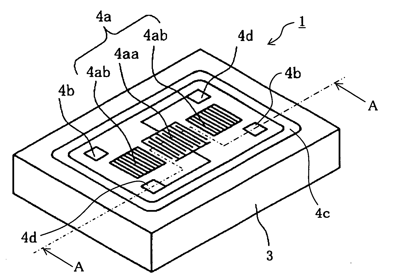
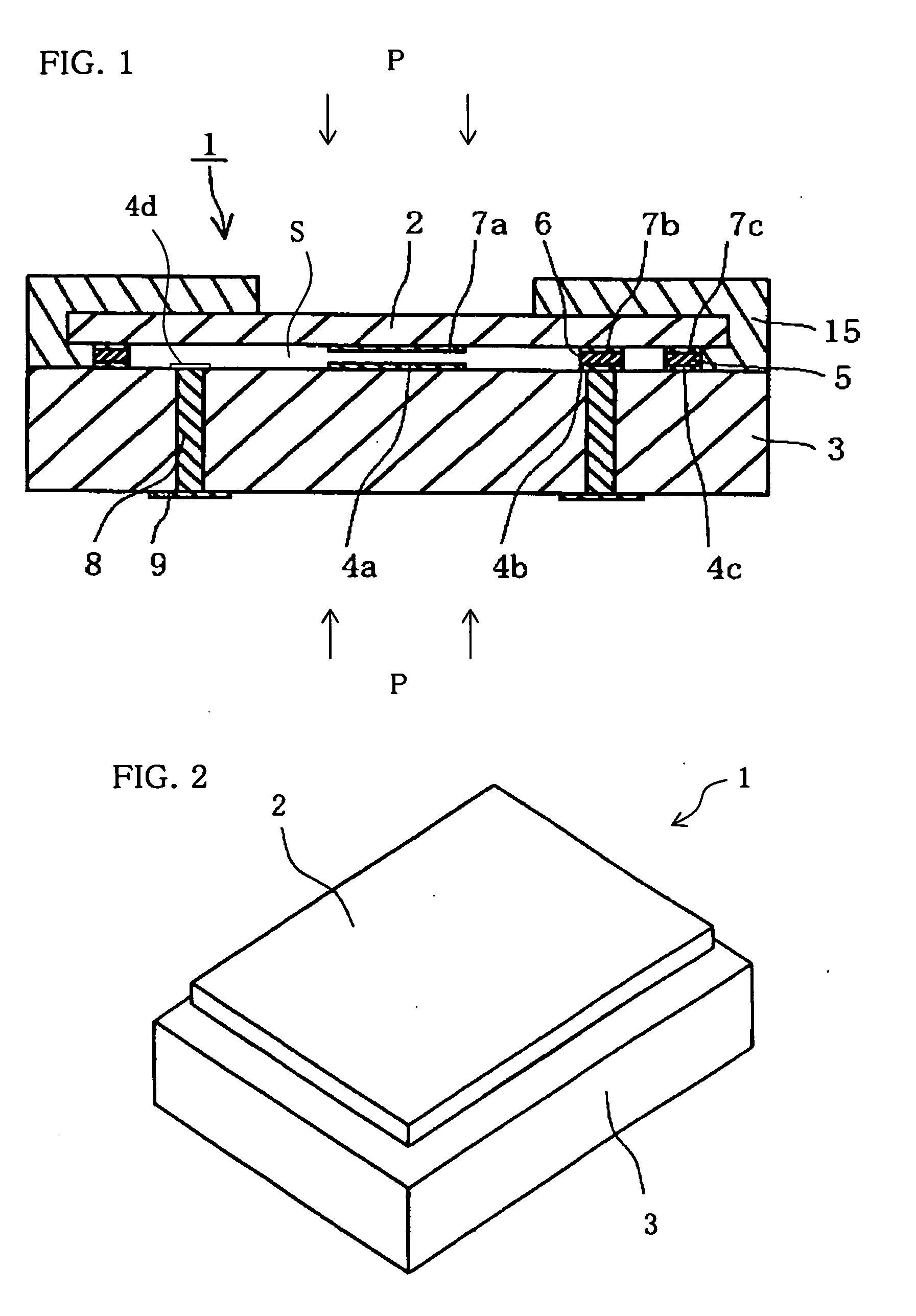
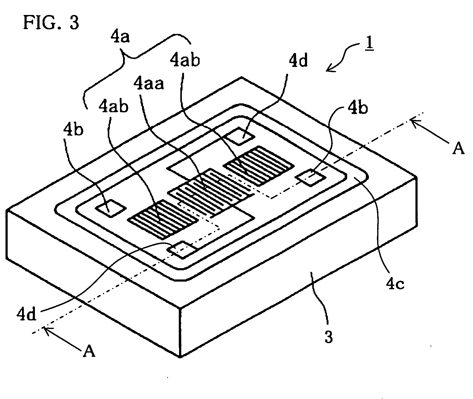
[0049]FIG. 1 is a sectional view of a pressure sensor device 1 according to an embodiment of the present invention, and FIG. 2 is an external perspective view of the pressure sensor device. FIG. 3 is an external perspective view showing a structure of a surface acoustic wave element for reference disposed on a supporting piezoelectric substrate used in the pressure sensor device 1.

[0050]FIG. 1 is a sectional view of the supporting piezoelectric substrate 3 taken along line A-A of FIG. 3. The protecting material 15 in FIG. 2 is omitted.

[0051]FIG. 1 is a sectional view of the supporting piezoelectric substrate 3 taken along line A-A of FIG. 3. The protecting material 15 in FIG. 2 is omitted.

[0052] The pressure sensor device 1 is chiefly made up of the supporting piezoelectric substrate 3 provided with a surface acoustic wave element for reference 4a, a pr...


PUM

PropertyMeasurementUnit
thicknessaaaaaaaaaa
thicknessaaaaaaaaaa
thicknessaaaaaaaaaa

Abstract

Thickness of a pressure-detecting piezoelectric substrate (2) that is thinner than that of a supporting piezoelectric substrate (3) and that has a surface acoustic wave element for pressure detection (7a) on its lower surface is mounted on the supporting piezoelectric substrate (3) having a surface acoustic wave element for reference (4a) on its upper surface. A sealing member (5) is provided between the supporting piezoelectric substrate (3) and the pressure-detecting piezoelectric substrate (1). The surface acoustic wave element for pressure detection (7a) and the surface acoustic wave element for reference (4a) can be disposed in a space (S) enclosed with the pressure-detecting piezoelectric substrate (1) and the sealing member (5). It is possible to provide a small-sized pressure sensor device (1) that can perform temperature compensation and that has high reliability.

Description

BACKGROUND OF THE INVENTION [0001] 1. Field of the Invention [0002] This invention relates to a pressure sensor device for detecting gas or liquid pressure fluctuations and oscillating an electric signal, the pressure sensor device being used, for example, to monitor the air pressure of a tire. [0003] 2. Description of the Related Art [0004] A device of a type that detects the fluctuation of applied pressure as a change in oscillation frequency has been conventionally used as a pressure sensor device for detecting gas or liquid pressure fluctuations. [0005] As an example of this type of conventional pressure sensor device, there is known a pressure sensor device having a structure in which surface acoustic wave elements 54 and a surface acoustic wave element 57 each of which is formed of a pectinate electrode are disposed on a piezoelectric substrate 51, and in which a region where the surface acoustic wave element 54 is formed is set to be thinner in thickness than a region where t...

Claims


Application Information

Patent Timeline
Patent Type & Authority Applications(United States)
IPC IPC(8): G01L9/00
CPCG01L9/0025
Inventor OIKAWA, AKIRAMATSUO, KAORUTACHIOKA, HIROSHI
Owner KYOCERA CORP
Why Eureka
Try Eureka