Control device for a fluid flow rate

Inactive Publication Date: 2007-05-17
SUNBIRD INVESTMENTS
View PDF4 Cites 0 Cited by
  • Summary
  • Abstract
  • Description
  • Claims
  • Application Information

AI Technical Summary

Benefits of technology

[0010] The technical aim of the present invention is therefore to provide a control device

Problems solved by technology

However, to carry out inspection, checking and maintenance operations on the dispenser, the dispenser has to be disconnected from the lubricant feed line, with all the associated problems of maintaining the plant at rest and the removal and assembly problems which

Method used


Image

  • Control device for a fluid flow rate
  • Control device for a fluid flow rate
  • Control device for a fluid flow rate

Examples


Embodiment Construction

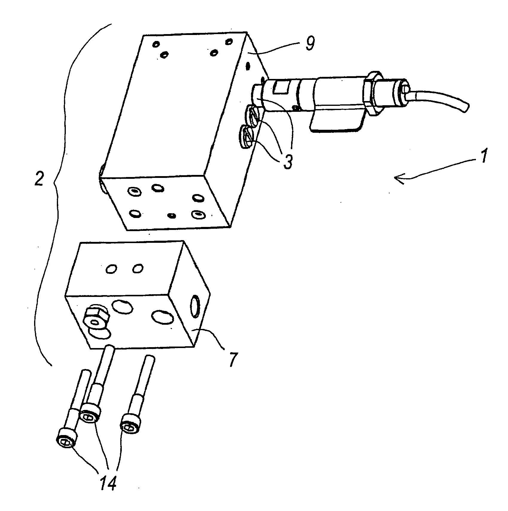
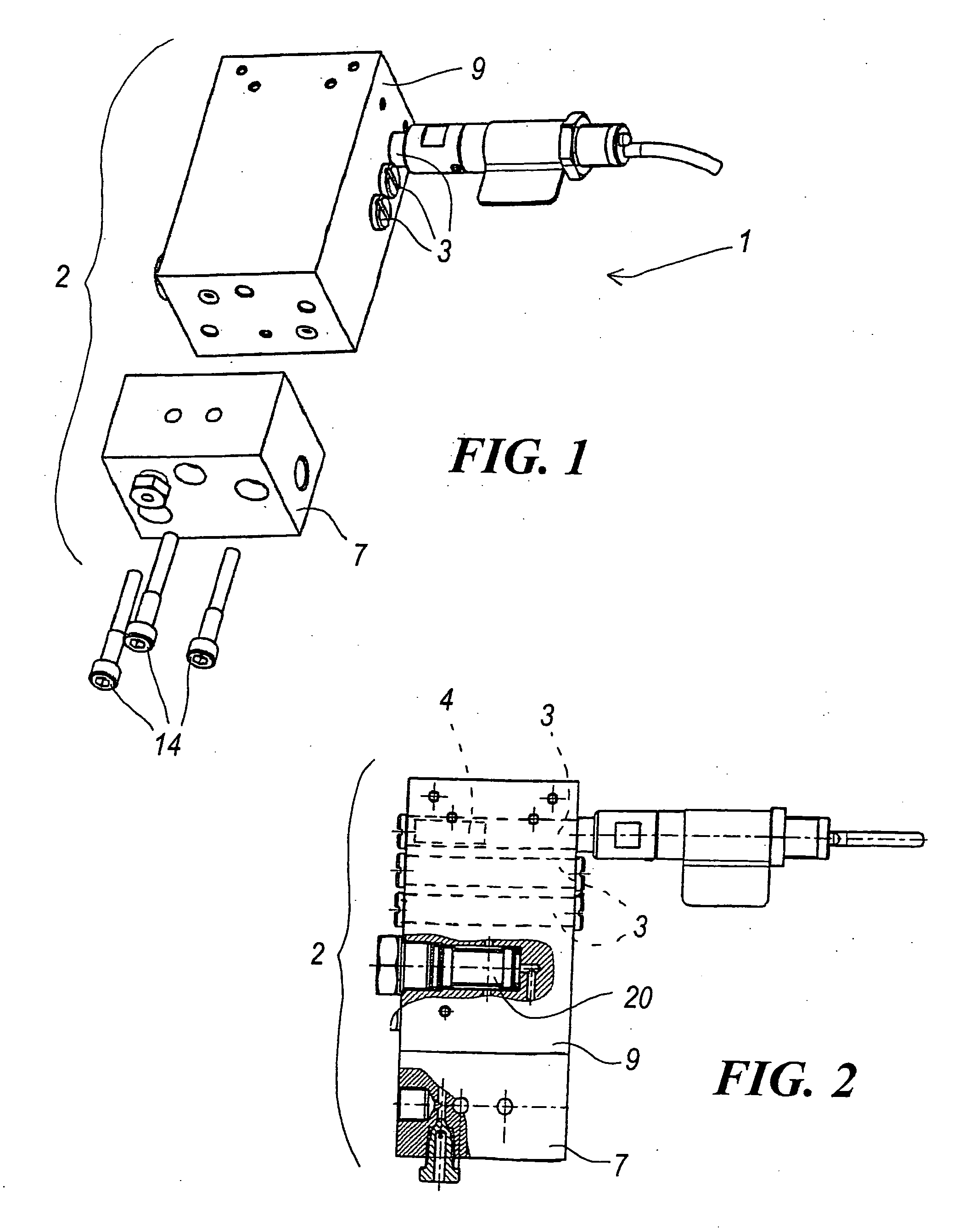
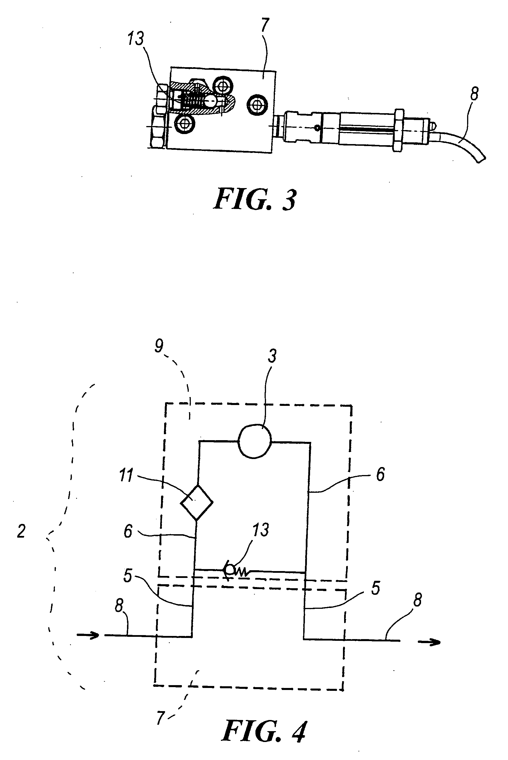
[0020] With reference to said figures, these show a fluid flow rate control device indicated overall by the reference numeral 1.

[0021] The device 1 comprises a body 2 defining a plurality of first chambers 3, one of which (in the illustrated embodiment) houses a piston 4; the first chambers 3 are connected together and to the outside by fluid transfer conduits 5, 6.

[0022] The chamber 3 (and the piston 4 slidable therein) operates as a volumetric flow metering chamber; in other embodiments in which the other first chambers 3 are also provided with a piston, the chambers 3 can operate as a flow divider.

[0023] Advantageously, the body 2 comprises a first portion 7 connectable to a fluid delivery line 8 and provided with first transfer conduits 5 connectable (and shown connected in FIG. 4) to the fluid delivery line 8.

[0024] The body 2 also comprises a second portion 9 removably connected to the first portion 7 (i.e. connected in a manner enabling it to be demounted). The second por...


PUM


Abstract

The control device for a fluid flow rate comprises a body defining at least one first chamber housing a piston and connected to the outside via fluid transfer conduits. The body comprises a first portion connectable to a delivery line for said fluid and provided with first transfer conduits connectable to the delivery line for the fluid, and a second portion removably connected to the first portion. The second portion defines the first chambers connected to second transfer conduits, themselves connected to the first transfer conduits.

Description

FIELD OF THE INVENTION [0001] The present invention relates to a control device for a fluid flow rate; reference will be made hereinafter specifically to devices which measure and / or divide the flow rate of lubricant fluids. BACKGROUND OF THE INVENTION [0002] Lubricant fluids are known to require very precise dispensing, particularly in minimal lubrication applications, in which lubrication is provided by a thin film of fluid interposed between the parts in relative movement. In these cases the flow rate must not be too low because in that case the fluid film would be interrupted, and direct contact (i.e. not through the fluid film) would exist between the members in relative movement. [0003] Neither must the flow rate be too large, because in that case the considerable fluid quantity would generate intense viscous forces which would hinder movement. [0004] Hence to ensure that the correct lubricant flow rate is fed, a control device is usually inserted into lubricant fluid feed lin...

Claims


Application Information

Patent Timeline
IPC IPC(8): F17D1/00
CPCF16N25/02Y10T137/87885
Inventor DIVISI, WALTER
Owner SUNBIRD INVESTMENTS
Why Eureka
Try Eureka