Debarking tip assembly with replaceable cutting element

a technology of swing arm and cutting element, which is applied in the direction of turning apparatus, turning machine accessories, tree debarking, etc., can solve the problems of affecting the service life of the machine, so as to achieve the effect of keeping the stress sufficiently low

Active Publication Date: 2010-06-29
NICHOLSON MFG
View PDF10 Cites 3 Cited by
  • Summary
  • Abstract
  • Description
  • Claims
  • Application Information

AI Technical Summary

Benefits of technology

[0006]Some embodiments disclosed herein include the realization that swing arm assemblies of a debarker apparatus can have one or more replaceable cutting elements for processing logs (e.g., debarking, scraping, slicing, or otherwise processing logs or other manufacturing materials). The cutting elements may be subjected to cyclic loading that rapidly dulls the cutting elements. In some embodiments, the cutting elements are comprised mostly of a high wear resistant material, such as a hardened material, for a prolonged life. If the cutting elements are not performing properly, the cutting elements can be quickly replaced with limited machine downtime. After the cutting elements have been worn a predetermined amount, the cutting elements can be quickly replaced.
[0007]A cutting element can be conveniently replaced with other angled cutting elements to adjust cutting action. In some embodiments, a cutting element can be quickly replaced with another cutting element to increase or decrease the aggressiveness of the swing arm assembly. A kit can have a plurality of cutting elements, wherein each cutting element terminates in a different angled leading edge for debarking.
[0008]At least one fastener, in some embodiments, can be provided that prevents (under standard operating conditions) the cutting element from being pulled out of the receiving channel when the at least one fastener is installed in a hole in the swing arm and the clamp assembly is in the closed configuration. In some embodiments, a pair of spaced apart fasteners can be used to keep the clamp assembly in the closed configuration.

Problems solved by technology

The cutting elements may be subjected to cyclic loading that rapidly dulls the cutting elements.
If the cutting elements are not performing properly, the cutting elements can be quickly replaced with limited machine downtime.

Method used


Image

  • Debarking tip assembly with replaceable cutting element
  • Debarking tip assembly with replaceable cutting element
  • Debarking tip assembly with replaceable cutting element

Examples


Embodiment Construction

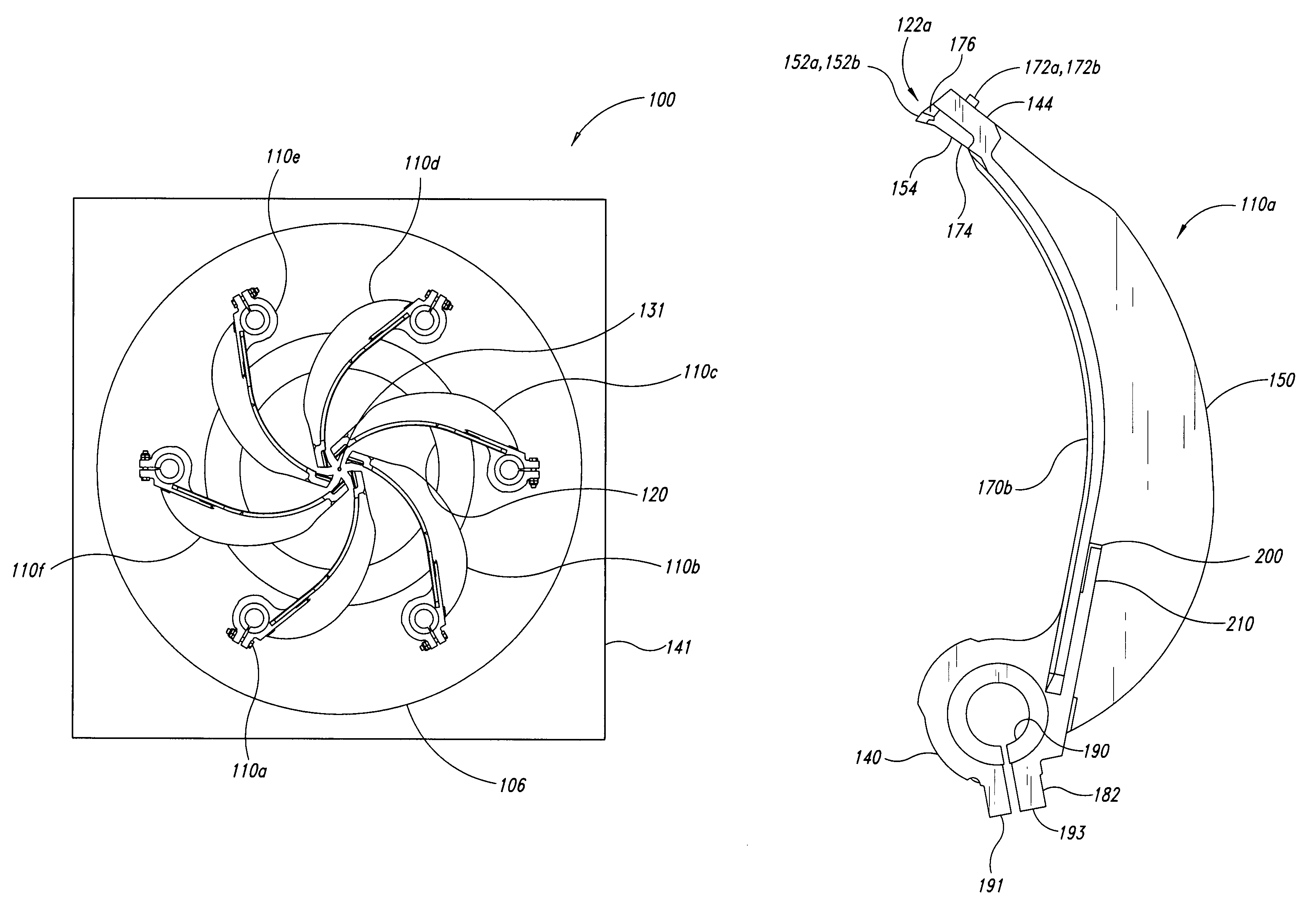
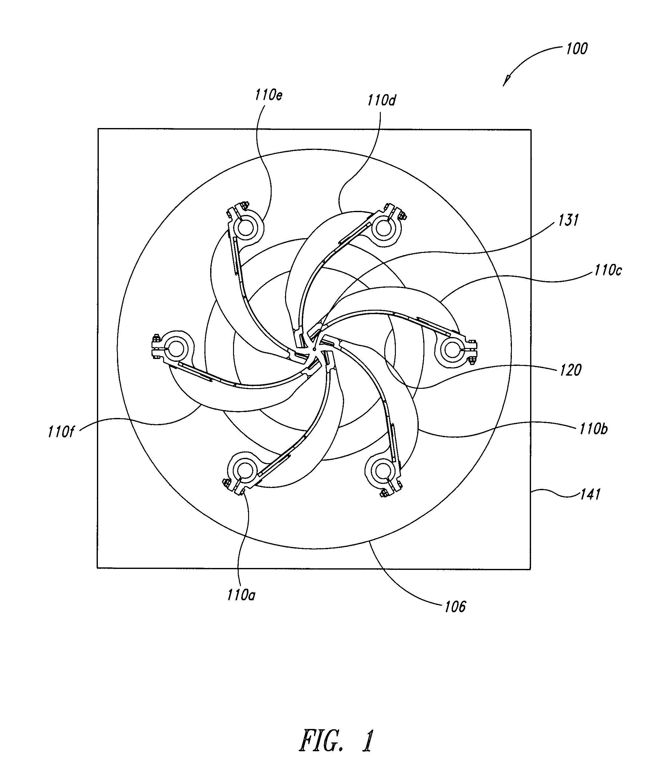
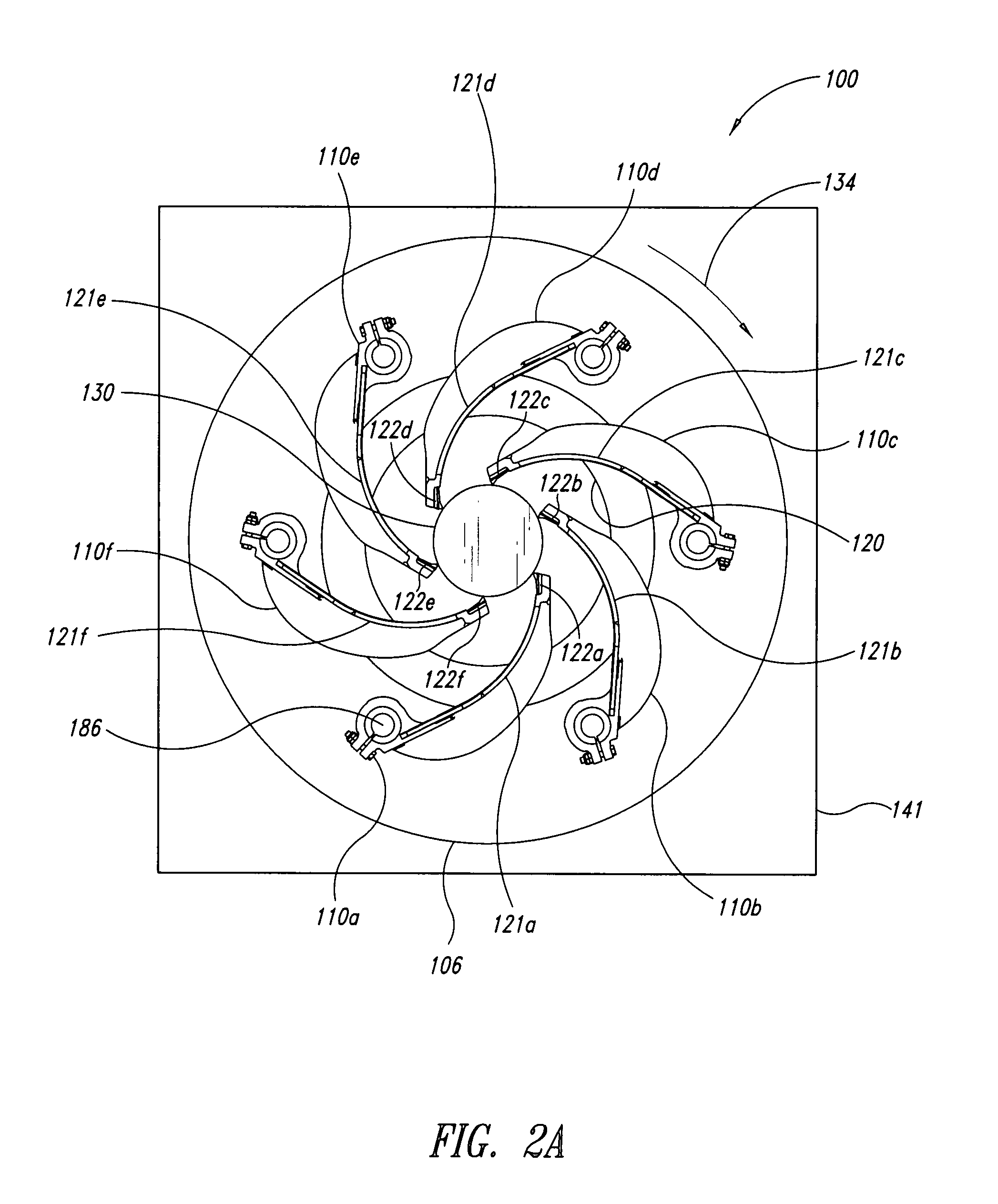
[0047]The present detailed description is generally directed towards a debarker apparatus with a plurality of swing arm assemblies, each having at least one debarker tip assembly. Some embodiments of the debarker tip assemblies have replaceable cutting elements that define contact features, such as leading edges, for engaging logs. Many specific details of certain exemplary embodiments are set forth in the following description and in FIGS. 1-29 to provide a thorough understanding of such embodiments. One skilled in the art, however, will understand that the disclosed embodiments may be practiced without one or more of the details described in the following description.

[0048]Additionally, the debarker tip assemblies are disclosed in the context of swing arms for log debarkers because they have particular utility in this context. However, the debarker tip assemblies can also be used in other contexts to scrape, roughen, slice, grind, or otherwise process logs, lumber, and the like. T...


PUM


Abstract

Apparatuses, systems, and methods for debarking logs are shown and described. The disclosed embodiments can be used for quickly and conveniently replacing contact surfaces of swing arm assemblies. Some disclosed embodiments include a swing arm assembly having a debarker tip assembly with a plurality of replaceable cutting elements for engaging logs moving along a processing line. Side-by-side cutting elements can be made of a wear resistant material for a prolonged life. A worn cutting element can be replaced with another cutting element to ensure proper functioning of the debarker apparatus.

Description

BACKGROUND[0001]1. Technical Field[0002]The present disclosure generally relates to debarker apparatuses, and more specifically to debarker apparatuses having swing arm assemblies with debarking tip assemblies with at least one replaceable cutting element.[0003]2. Description of the Related Art[0004]Rotary log debarkers, commonly referred to as ring debarkers, are used to remove bark from logs to facilitate processing of the logs into lumber and other wood products. Rotary log debarkers often have an array of swing arms pivotally mounted to a rotatable outer ring. Each of the swing arms has a cutting tip for scraping bark from the logs. As a log moves along a processing line of a traditional debarker, the advancing log contacts and pushes against the swing arms. The log then drives the swing arms outwardly until cutting tips of the swing arms engage the periphery of the log. The swing arms are then urged inwardly such that the cutting tips scrape bark off the log in a somewhat spira...

Claims


Application Information

Patent Timeline
Patent Type & Authority Patents(United States)
IPC IPC(8): B27L1/00
CPCB23B27/1625B27L1/08B23B2205/16B23B2200/163
Inventor LEFSRUD, JORGEN
Owner NICHOLSON MFG
Why Eureka
Try Eureka