Stemless shoulder implant

a stemless, shoulder technology, applied in the field of humerus implants, can solve the problems of implant rotational symmetry and implant misplacement, and achieve the effects of low bone removal, high retention force, and fixed procedur

Active Publication Date: 2016-12-06
ARTHREX
View PDF23 Cites 36 Cited by
  • Summary
  • Abstract
  • Description
  • Claims
  • Application Information

AI Technical Summary

Benefits of technology

[0009]The embodiments are based on the object of providing a humerus implant which may be used as part of a shoulder prosthesis and which can be securely fixed within the humerus with minimal removal of bone material. The fixation procedure should be simple and quick. A good fixation shall be achieved immediately after insertion, without cementing, so that the joint can be used immediately after insertion. A high retention force should be achieved. A precise placement and orientation of the implant should be possible.
[0010]In an embodiment, the humerus implant has a cup shaped body having flexible sidewall segments connected together at a center portion. There may be any number of sidewall segments between 2 and 24. Preferably, six sidewall segments are provided. There are at least two different types of sidewall segments. Whereas the sidewall segments basically have the same inner contour, they differ in the outer shape, which has to provide a stable, secure and long-lasting contact with the surrounding bone. Preferably, four first sidewall segments and two second sidewall segments are provided. The different types of sidewall segments are optimized for different properties. A first type of sidewall segments preferably has a plurality of locking fins, which immediately anchor the cup shaped body within the bone. Due to the radial anchoring in the bone material, the fins cause a comparatively high pull out force of the implant. Further cementing is no more necessary. A second type of sidewall segments preferably has a structure of recesses and holes, which allow ingrowth of the bone. The recesses increase the pull out force of the cup shaped body, while the holes block rotation. Preferably, the at least two types of sidewall segments are at least partially arranged alternating. This allows for a good distribution of the properties of both kinds of sidewall segments over the circumference of the cup shaped body. To allow insertion of the cup shaped body into a bone, gaps are provided between the individual sidewall segments. Accordingly, the gaps are between neighbored segments. These allow a slight compression of the sidewall segments during insertion and therefore a reduction of the outer circumference of the cup shaped body. Due to be reduced circumference, the cup shaped body can easily be inserted into a hole of the bone.
[0011]It is further preferred, if there is at least one, preferably two tabs, close to the upper side of one or two sidewall segments and extending radially from the cup shaped body. The at least one tabs preferably are essentially parallel to plane defined by the upper ends of the sidewall segments. They allow for a precise alignment of the cup shaped body. First, the cup shaped body may be aligned, so that at least one tabs are located on the bone surface. This allows an alignment of the tilt of the cup shaped body. With implants, known from prior art, a spherical implant can be inserted into a spherical hole under any tilt angle. This may lead to a misplacement of the implant. When the at least one tabs contact the bone surface, the implant is parallel to the bone surface, without any tilt error. Therefore, the insertion alignment is improved. The at least one tabs further increase stability of the implant immediately after insertion. When the implant is correctly installed and the at least one tabs contact the bone surface, they can provide additional load bearing capacity and optional tilt moment and therefore increase the stability significantly.
[0015]According to another embodiment, the humerus implant has a cup shaped body having sidewalls between a top side and a bottom side. At the outside of the body is a thread having a plurality of fins starting with a first fin and ending with a last fin. There are cutouts between the fins. The fins are specifically designed to secure the body within the bone even without cementing. Due to the radial anchoring in the bone material, the fins cause a comparatively high pull out force of the implant. At least one fin, preferably a plurality of fins, most preferably all fins have an inclined leading surface which helps in incising into the bone by rotating the body in an inward direction. By this measure, the insertion torque is minimized. The inclination of the leading surface may also be negative resulting in an undercut leading surface. There may be a combination of different types of fins in one thread. Furthermore at least one fin, preferably a plurality of fins, most preferably all fins have a forward oriented undercut trailing surface. This results in an angle of less than 90 degrees between a top surface and the trailing surface, blocking rotation in the opposite, outward direction. Therefore, the removal torque is maximized. Between the individual fins there are cutouts leaving room for abraded bone material and therefore further reducing the insertion torque and avoiding chattering. Tests have proven that this thread design results in removal torques similar to and preferably at least 60% of insertion torques immediately after insertion and without any recovery period allowing further bone growth into the structure. Due to such bone growth, the removal torque increases further with time.
[0017]By filling the cutouts with cement or bone grafts or substitutes the stability may further be increased.
[0021]In the most preferred embodiment, it is designed to provide a combination interface for a joint adapter to interface with the glenoid component of a reverse prosthesis and the humeral component of an anatomical prosthesis. Here specifically the cup shape allows a more simple and robust interface for the humeral component of an anatomical prosthesis, which for example may be held by a Morse taper. This embodiment allows simple replacement of an anatomical prosthesis by a reverse prosthesis during revision. Here exchanging of a prosthesis stem is no more necessary. Even the implant can remain in place, as only the heads must be exchanged.

Problems solved by technology

This may lead to a misplacement of the implant.
Therefore, the implant may not be rotational symmetrical.

Method used


Image

  • Stemless shoulder implant
  • Stemless shoulder implant
  • Stemless shoulder implant

Examples


Embodiment Construction

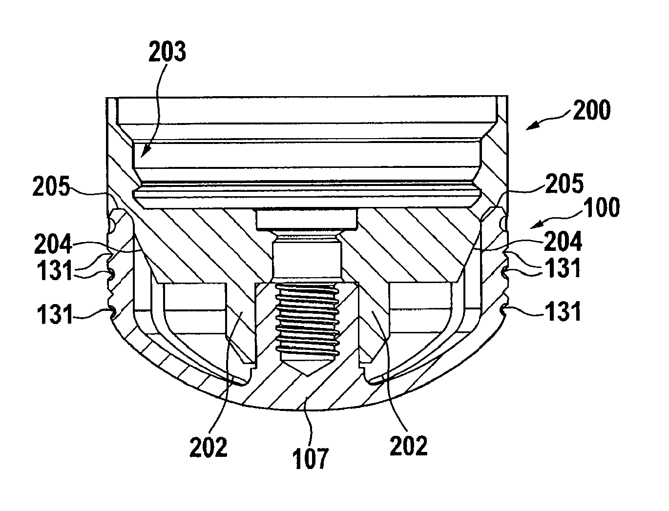
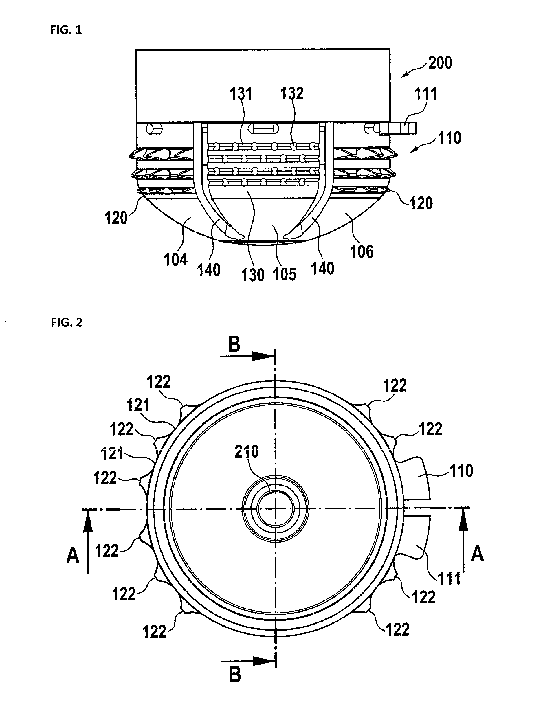
[0041]FIG. 1 shows an embodiment of a humerus implant in a side view. The implant has a cup shaped body 100, which include of a plurality of sidewall segments. There are first sidewall segments 104, 106, 120 having locking fins 122. These locking fins immediately anchor the cup shaped body within the bone. Due to the radial anchoring in the bone material, the fins cause a comparatively high pull out force of the implant. Further cementing is no more necessary.

[0042]Second sidewalls 130 have recesses 131 and holes 132, which allow ingrowth of the bone. The recesses increase the pull out force of the cup shaped body, while the holes block rotation. Preferably, there are gaps 140 between the sidewall segments, which allow a compression of the sidewall segments during insertion and therefore a reduction of the outer circumference of the cup shaped body. Due to be reduced circumference, the cup shaped body can easily be inserted into a hole of the bone. At least one tab 111 is provided f...


PUM


Abstract

A humerus implant includes a cup shaped body and a locking adapter. The cup shaped body has a center portion and a plurality of flexible first sidewall segments and second sidewall segments, with gaps between neighbored sidewall segments. The first sidewall segments have a plurality of locking fins while the second sidewall segments having a plurality of recesses and holes. The locking adapter has means for fixing the locking adapter to the cup shaped body and a locking ring for locking the sidewall segments into their final positions.

Description

PRIORITY CLAIM[0001]This application claims priority to pending European Application No. 13172917.0 filed on 19, Jun. 2013.BACKGROUND OF THE INVENTION[0002]1. Field of the Invention[0003]The present invention relates to a shoulder arthroplasty system to surgical reconstitution of the shoulder and, in particular, to a humerus implant.[0004]2. Description of Relevant Art[0005]The shoulder joint is a ball-and-socket joint, which has an exceptional range of motion. Shoulder instability and other maladies of the shoulder joint, such as arthrosis or fracture, may require a replacement of the joint.[0006]A shoulder joint prosthesis, which includes the replacement of the convex head of the humerus, is disclosed in U.S. Pat. No. 7,819,923. It reflects the orientation and the center of rotation of actual joints. In the case of a worn or damaged rotator cuff or too much bone loss, such prosthesis would not recover the range of motion. In such a case, a reverse shoulder prosthesis may be prefer...

Claims


Application Information

Patent Timeline
Patent Type & Authority Patents(United States)
IPC IPC(8): A61F2/30A61F2/40
CPCA61F2/4014A61F2/4003A61F2002/30332A61F2002/30433A61F2002/30571A61F2002/30579A61F2002/30784A61F2002/30822A61F2002/30881A61F2002/4018A61F2002/4022
Inventor BACHMAIER, SAMUEL
Owner ARTHREX
Why Eureka
Try Eureka