Image recording apparatus

Inactive Publication Date: 2007-05-17
FUJIFILM CORP
View PDF20 Cites 13 Cited by
  • Summary
  • Abstract
  • Description
  • Claims
  • Application Information

AI Technical Summary

Benefits of technology

[0067] Further, there is no need to move the guide member used at the time of the parallel transport in the direction perpendicular to the transport plane, so the positional accuracy for the guide member is high, that is, it is possible to ensure in a stable manner high positional accuracy in the width direction for the recording medium, making it possible to perform proper image recording.
[0068] Further, the pair of outer guides arranged in the width direction of the transport plane and the pair of inner guides arranged between the pair of outer guides are movable symmetrically with respect to the central position in the width direction of the transport path and independently of each other, so it is possible to regulate the recording medium to the transport path in the width direction with high degree of freedom, making it possible to perform the image recording on recording media of various sizes (widths).
[0069] Further, as stated above, in the image recording apparatus of another embodiment according to the second aspect of the present invention, the pair of outer guides and the pair of inner guides are movable symmetrically with respect to the central position in the width direction of the transport path and independently of each other, so it is po

Problems solved by technology

However, the regulating guide disclosed in Patent Document 2 can only be applied to two types of transport, that is, the single-line transport and the parallel transport in a fixed number of lines, for example, two lines, resulting in a rather low degree of freedom.
Further, in the regulating guide disclosed in Patent Document 2, it is necessary to provide the retreat mechanism for causing the central guide to retreat completely from the transport plane for the single-line transport, with the result that the image forming apparatus is rather large and complicated.
Further, due to its construction, in this regulating guide, the central guide which serves as the positional reference in the width direction for the rec

Method used


Image

  • Image recording apparatus
  • Image recording apparatus
  • Image recording apparatus

Examples


Example

[0095] In the following, preferred embodiments of the image recording apparatus of the present invention will be described in detail with reference to the accompanying drawings.

[0096] The image recording apparatus of the first aspect of the present invention will be explained referring to FIGS. 1 to 7. First, an ink jet printer which applies the image recording apparatus of each of the first to third aspects of the present invention will be explained.

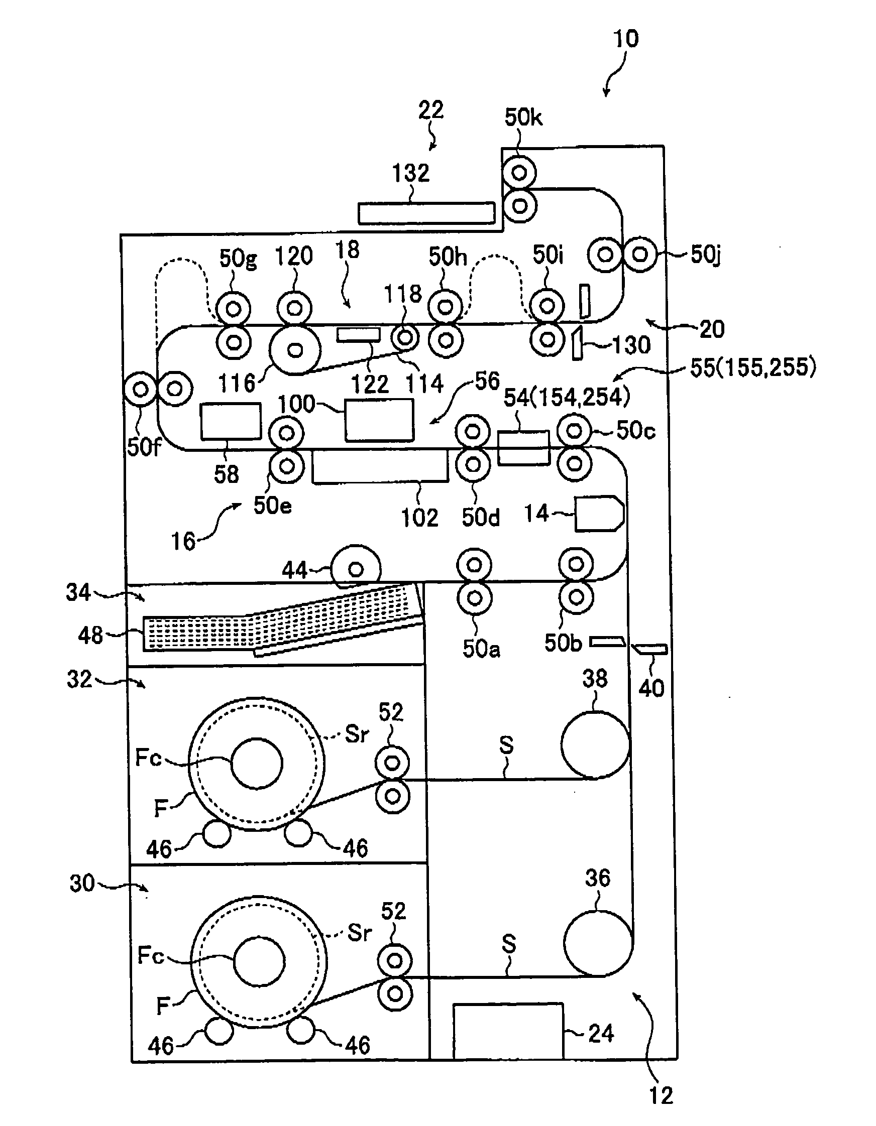
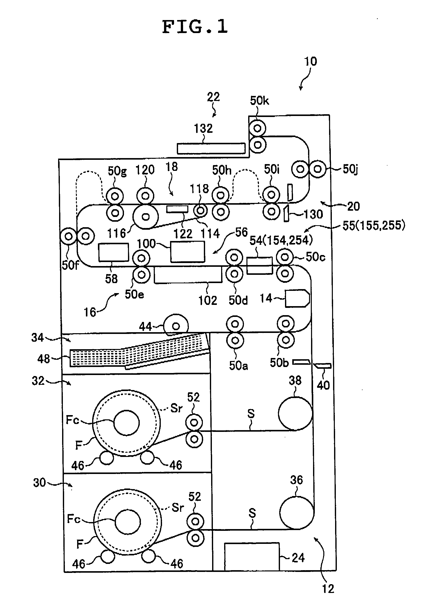
[0097]FIG. 1 is a conceptual drawing showing one embodiment of the ink jet printer using the image recording apparatus according to the present invention.

[0098] An ink jet printer shown in FIG. 1 (hereinafter referred to as a printer) 10 performs, on a recording sheet S, not only image recording by ink jet but also, as needed, a surface treatment for realizing back printing and a quality equivalent to that of a photograph before outputting a print. The printer 10 basically comprises a recording sheet supplying section 12, a back prin...


PUM


Abstract

The image recording apparatus includes a regulating guide for regulating a position of a recording medium and a passage changing unit for changing a passage of the recording medium to the other passage thereof. The regulating guide includes a pair of outer guides arranged at outermost positions in a width direction and having in a perpendicular direction to a transport plane for the recording medium plural outer passage portions for regulating a position of the recording medium in the width direction and at least one inner guide arranged between the pair of outer guides and having on both sides in the width direction inner passage portions for regulating a position of the recording medium in the width direction at a position in the perpendicular direction corresponding to one outer passage portion of the pair of outer guides. The regulating guide forms plural passages in the perpendicular direction.

Description

[0001] The entire contents of literatures cited in this specification are incorporated herein by reference. BACKGROUND OF THE INVENTION [0002] The present invention belongs to the technical field of an image recording apparatus such as an ink jet printer. In particular, the present invention relates to an image recording apparatus capable of achieving high productivity by transporting recording media in parallel as needed and capable of easily performing switching between parallel transport and single-line transport. [0003] As a method of achieving an enhancement in productivity in various types of image recording apparatus including an ink jet printer, there is known a method in which recording media are transported in a plurality of lines arranged in a direction (hereinafter referred to as the width direction) perpendicular to a recording medium transporting direction (hereinafter referred to as the parallel transport) and in which image recording (drawing) and a post-processing a...

Claims


Application Information

Patent Timeline
IPC IPC(8): B41J2/01
CPCB41J11/0055
Inventor TANABE, TSUYOSHI
Owner FUJIFILM CORP
Why Eureka
Try Eureka