Lure

Active Publication Date: 2022-03-03
SHIMANO INC
View PDF2 Cites 0 Cited by
  • Summary
  • Abstract
  • Description
  • Claims
  • Application Information

AI Technical Summary

Benefits of technology

[0014]In one embodiment, the swinging part is capable of moving even after the lure is brought from an operating (or moving) state to a stopped state.
[0015]In the lure according to an embodiment of the present invention, a rod comprises a rod portion, a flange portion is connected to the rod portion, and a projecting portion projects from the flange portion to the opposite side of the rod portion. One end of the rod portion is inserted into a rod hole of a first body part, the projecting portion is inserted into a

Problems solved by technology

However, with this lure, with the application of an external load, the body deforms and the abutting parts can shift.
This shifting can interfere with the operation of the incorporated mechanism.
For example, in the lure of Japanese Laid-Open Patent Application No. 2019-18724

Method used


Image

  • Lure
  • Lure
  • Lure

Examples


Example

[0021]The present invention will be described in detail below based on preferred embodiments and with reference to the drawings, as is suitable.

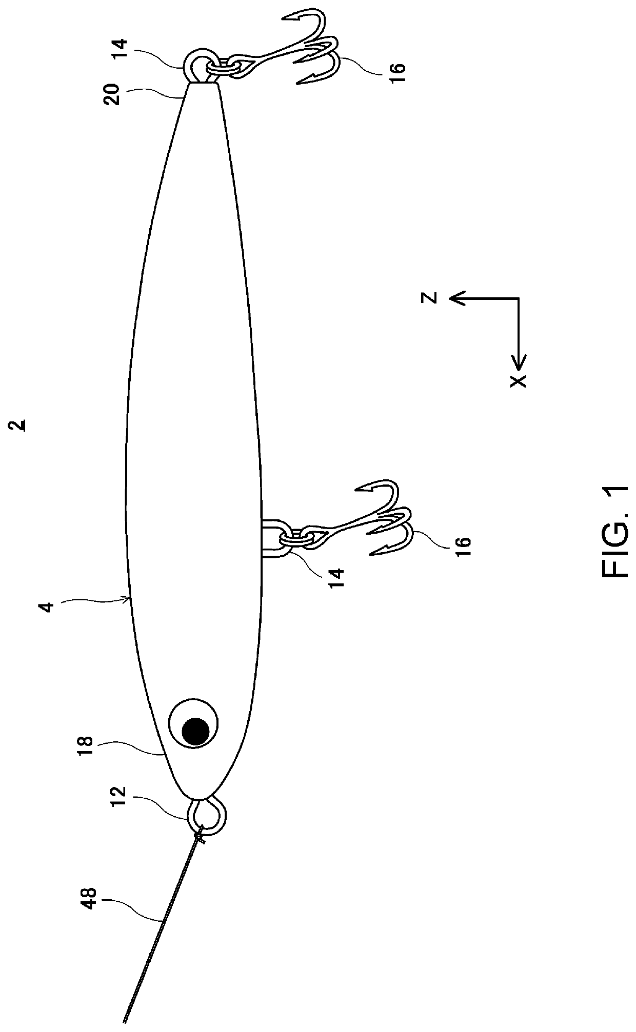
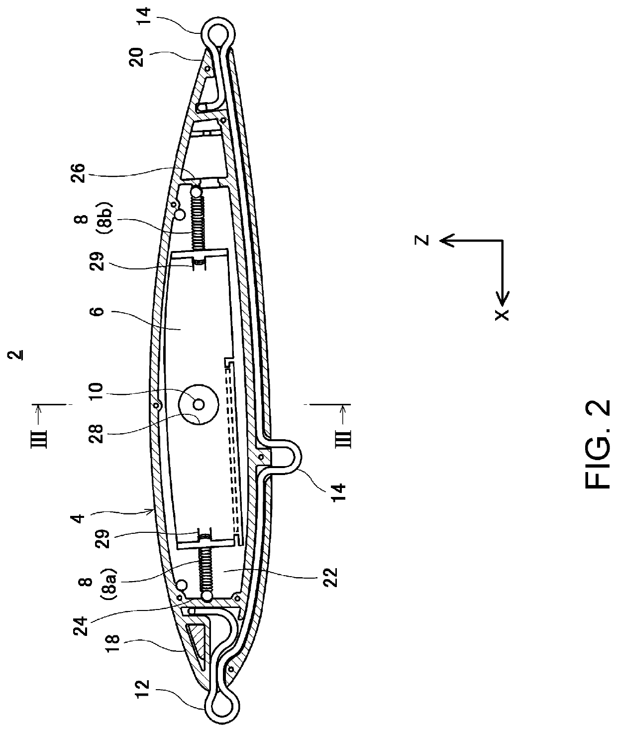
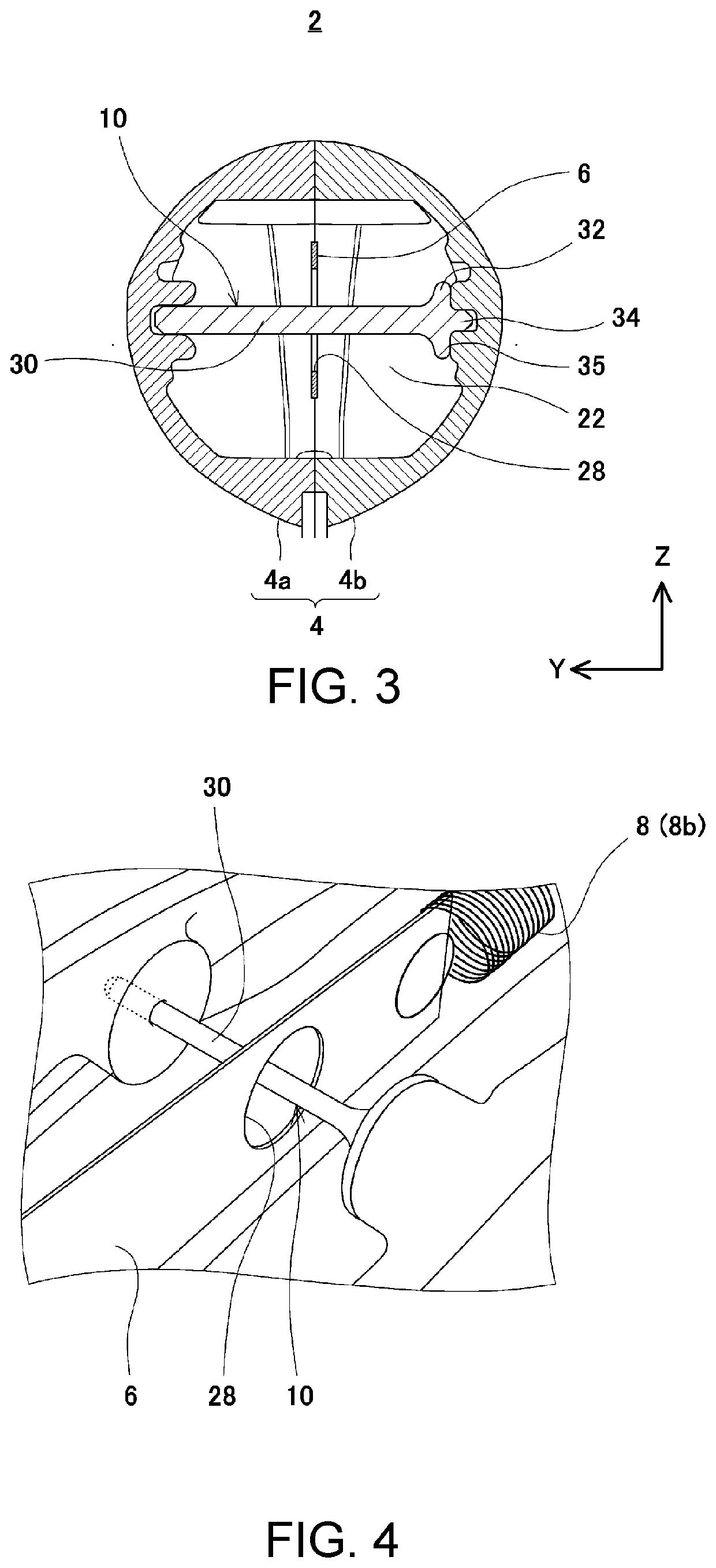
[0022]FIG. 1 is a side view illustrating a lure 2 according to one embodiment of the present invention. In FIG. 1, the direction indicated by arrow X is defined as the front of the lure 2, and the opposite direction is the defined as the rear of the lure 2. The direction indicated by arrow Z is defined as the upper side of the lure 2, and the opposite direction is defined as the underside of the lure 2. The direction perpendicular to the plane of the paper is the left-right direction of the lure 2. FIG. 2 is a cross-sectional view taken along the longitudinal direction of the lure 2 of FIG. 1. FIG. 3 shows a cross section through line of FIG. 2. In FIG. 3, the direction indicated by arrow Y is defined as the direction toward the right side of the lure 2, and the opposite direction is the defined as the direction toward the left side of the l...


PUM


Abstract

A lure includes a first and second body parts, a structure in which the first and second body parts are coupled together, and an interior cavity, and a rod bridging the first and second body parts in the interior cavity. The rod has a rod portion, a flange portion connected to a first end of the rod portion, and a projecting portion projecting from the flange portion to an opposite side of the rod portion. The first body part has an inner surface and a rod hole on the inner surface thereof. The second body part has an inner surface and a base projecting from the inner surface thereof, and a receiving hole recessed from the surface of the base. A second end of the rod portion is inserted into the rod hole, the projecting portion inserted into the receiving hole, and the flange portion in contact with the base.

Description

CROSS-REFERENCE TO RELATED APPLICATIONS[0001]This application claims priority to Japanese Patent Application No. 2020-142237, filed on Aug. 26, 2020. The entire disclosure of Japanese Patent Application No. 2020-142237 is hereby incorporated herein by reference.BACKGROUNDField of the Invention[0002]The present invention relates to a lure that is used for fishing.Background Art[0003]Large fish, such as largemouth bass, yellowtail and yellowtail juveniles, and sea bass, prey on small fish. These large fish are called fish eaters. Lure fishing is a popular way to catch fish eaters. In lure fishing, lures resembling bait, such as small fish, are used. The lure is cast and flies through the air, eventually landing in the water. The lure is designed to appear to be swimming through the water when the fishing line is taken up or reeled in. A fish eater, mistaking the lure for bait, bites the lure, and a hook attached to the lure is embedded in the fish eater. The fish eater can then be ree...

Claims


Application Information

Patent Timeline
IPC IPC(8): A01K85/01
CPCA01K85/01A01K85/00A01K85/18A01K85/16A01K85/015
Inventor NAKAMICHI, TADASUKE
Owner SHIMANO INC
Why Eureka
Try Eureka