Connector, mating connector and board-to-board connector assembly

a technology of connecting connectors and connectors, which is applied in the direction of connection contact member materials, fixed connections, coupling devices, etc., can solve the problems of speeding up signal transmission, difficulty in matching impedance between signal conductors and circuit patterns of the first and second circuit boards,

Inactive Publication Date: 2007-05-17
JAPAN AVIATION ELECTRONICS IND LTD
View PDF24 Cites 33 Cited by
  • Summary
  • Abstract
  • Description
  • Claims
  • Application Information

AI Technical Summary

Benefits of technology

[0006] The above-mentioned structure allows that the signal conductor is electrically connected to circuit patterns of circuit boards through the conductive resilient members without soldering. Therefore, it is easier than the disclosed technique to match impedance between the signal conductors and the circuit patterns of the circuit boards.

Problems solved by technology

However, the solder makes it difficult to match impedance between the signal conductors and the circuit patterns of the first and the second circuit boards.
The difficulty of the impedance-matching causes a problem on a high-speed signal transmission such as a differential transmission.

Method used


Image

  • Connector, mating connector and board-to-board connector assembly
  • Connector, mating connector and board-to-board connector assembly
  • Connector, mating connector and board-to-board connector assembly

Examples


Embodiment Construction

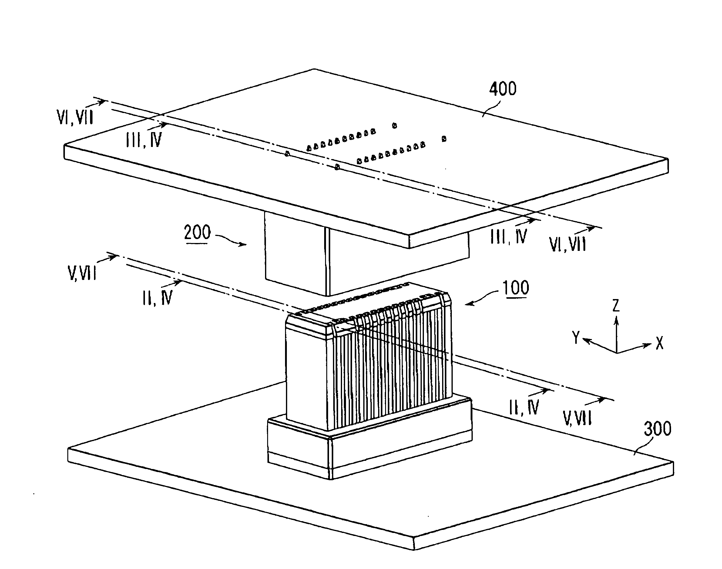
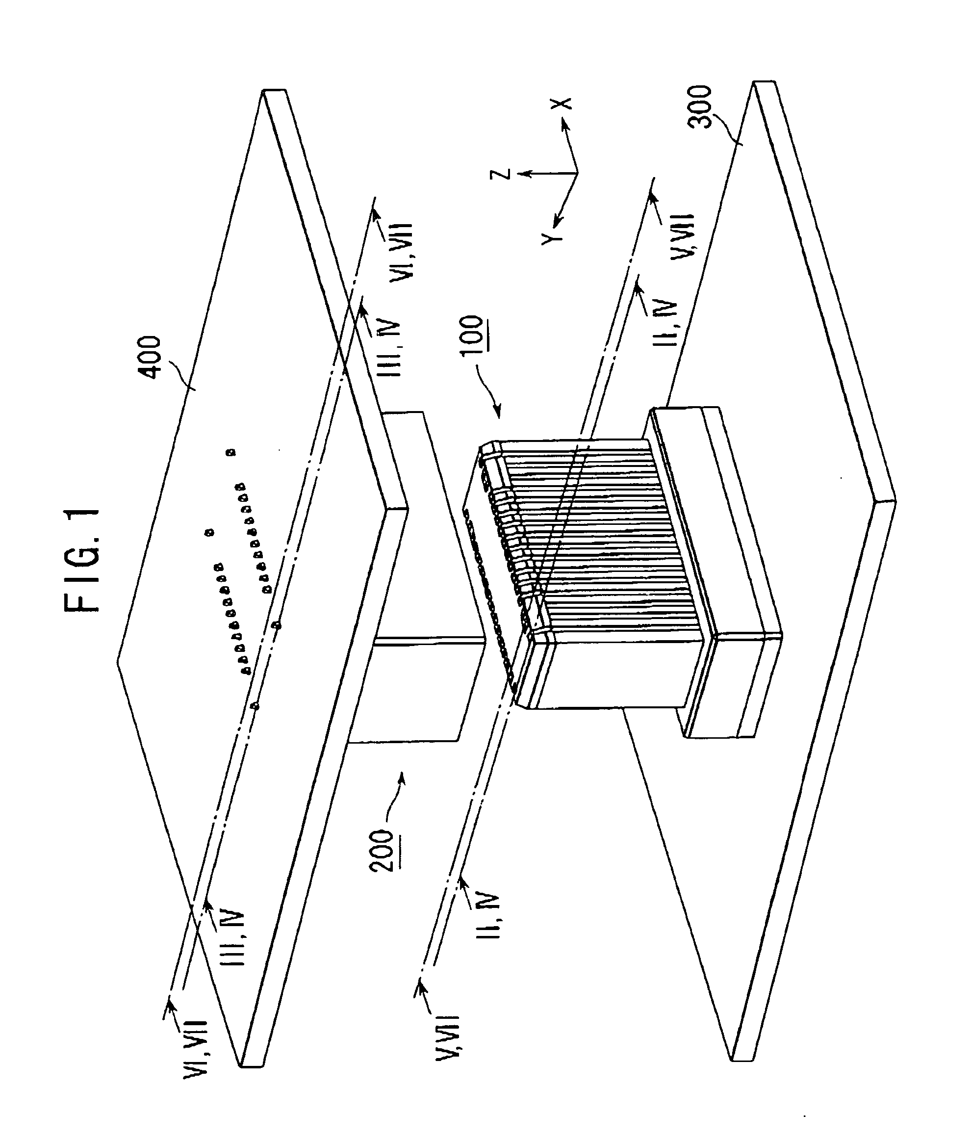
[0025] With reference to FIGS. 1 to 8, a connector assembly according to an embodiment of the present invention comprises a plug connector 100 having a fit portion and a receptacle connector 200 having a mating fit portion into which the fit portion of the plug connector 100 is press-fit to mate the plug connector 100 with the receptacle connector 200. The plug connector 100 is mounted and fixed on a circuit board 300. The receptacle connector 200 is mounted and fixed on another circuit board 400. When the plug connector 100 is mated with the receptacle connector 200, the circuit boards 300, 400 are interconnected by the connector assembly of the plug and the receptacle connectors 100, 200.

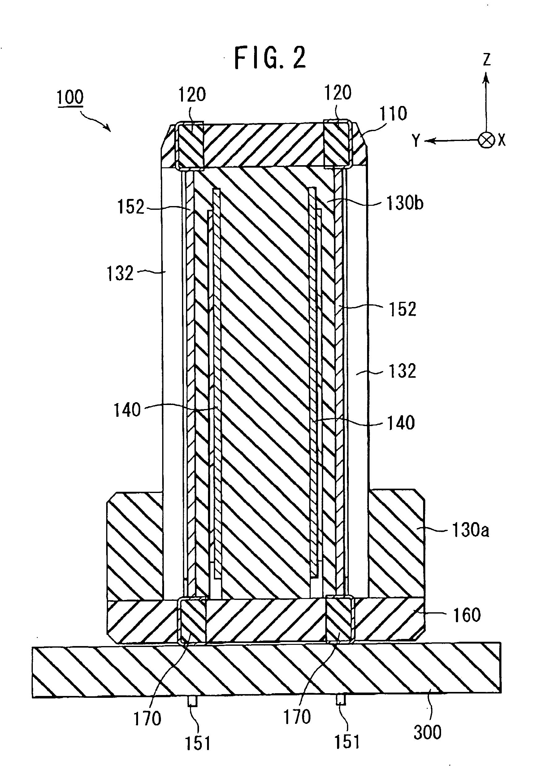
[0026] As shown in FIGS. 8 and 13, the plug connector 100 is generally comprised of three parts, i.e. an upper part, a middle part and a lower part. As shown in FIGS. 9 and 13, the upper part of the plug connector 100 comprises an upper block member 110 and conductive resilient members 120. As sh...


PUM


Abstract

A board-to-board assembly is disclosed, comprising a plug connector and a receptacle connector. One of the plug connector and the receptacle connector holds a signal conductor. The board-to-board assembly comprises conductive resilient members. The conductive resilient members provide electrical contacts between the signal conductor and circuit boards, respectively. No soldering process is required to the electrical contacts.

Description

BACKGROUND OF THE INVENTION [0001] This invention relates to a board-to-board connector assembly for use in connecting two circuit boards and, particularly, to a connector and a mating connector which constitute the board-to-board connector assembly. [0002] JP-A 2005-71769 discloses a board-to-board connector assembly comprising a plug connector and a receptacle connector, the contents of JP-A 2005-71769 being incorporated herein by reference. The plug connector is mounted on a first circuit board with its signal conductors such as terminals or contacts being soldered on a circuit pattern of the first circuit board so that the plug connector is fixed on the first circuit board. Likewise, the receptacle connector is mounted on a second circuit board with its signal conductors such as terminals or contacts being soldered on a circuit pattern of the second circuit board so that the receptacle connector is fixed on the second circuit board. Thus, all of the signal conductors of the disc...

Claims


Application Information

Patent Timeline
Patent Type & Authority Applications(United States)
IPC IPC(8): H01R13/648
CPCH01R9/096H01R12/58H01R23/688H01R12/52H01R13/6585
Inventor TOKUNAGA, TAKASHI
Owner JAPAN AVIATION ELECTRONICS IND LTD
Why Eureka
Try Eureka