Method of pacing travel speed

a technology of travel speed and speed, applied in the direction of welding/cutting media/materials, manufacturing tools, welding apparatus, etc., can solve the problems of limited visibility of welding helmets, and difficulty in pacing travel speed along test grooves

Inactive Publication Date: 2007-05-24
LINCOLN GLOBAL INC
View PDF13 Cites 77 Cited by
  • Summary
  • Abstract
  • Description
  • Claims
  • Application Information

AI Technical Summary

Problems solved by technology

This requirement presents practical difficulty.
The welder has limited visibility through a welding helmet.
Time is recorded, but there is no way for the welder to pace the travel speed along the test groove.
This requires skill, practice and trial and error.

Method used


Image

  • Method of pacing travel speed
  • Method of pacing travel speed
  • Method of pacing travel speed

Examples


Embodiment Construction

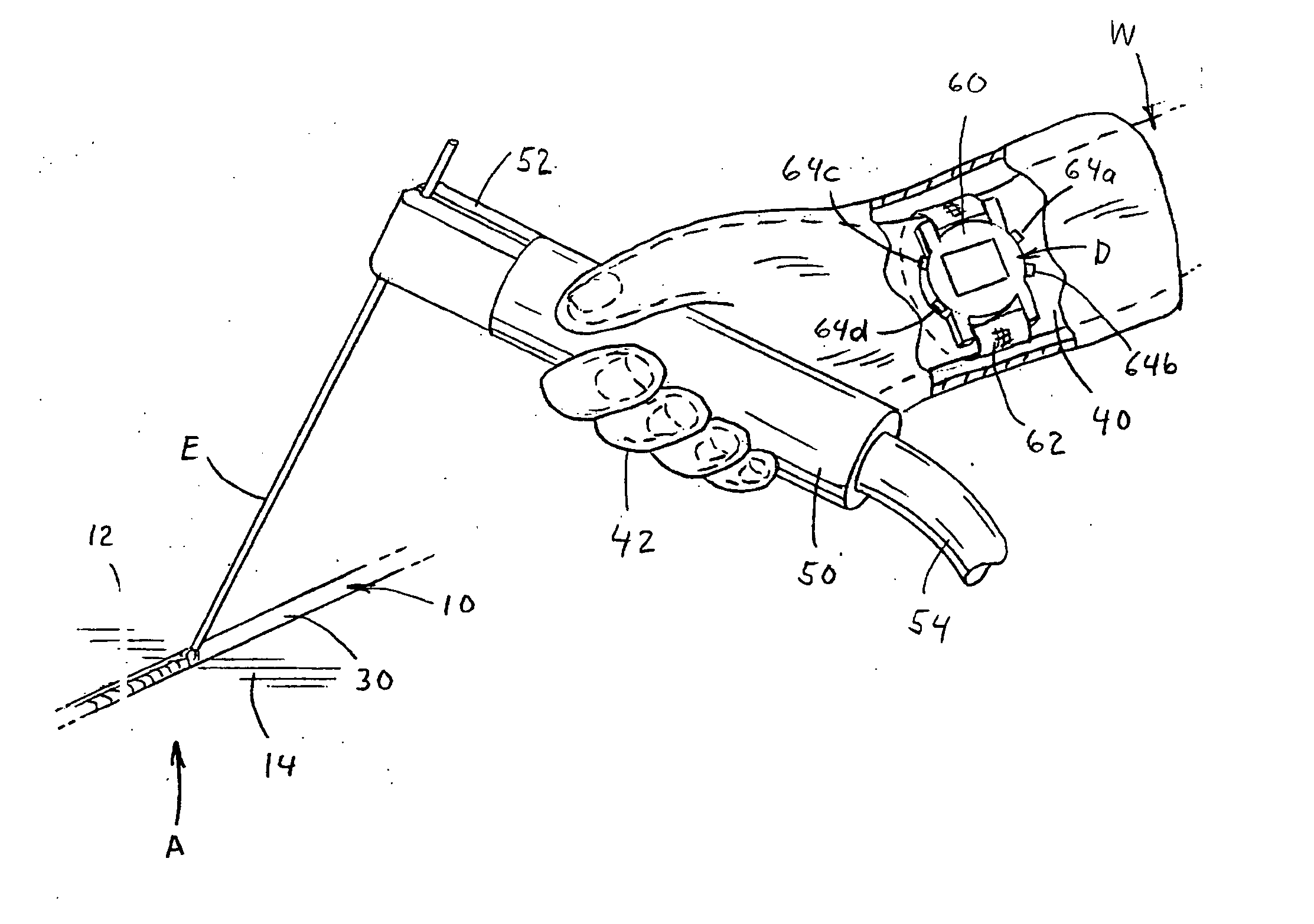
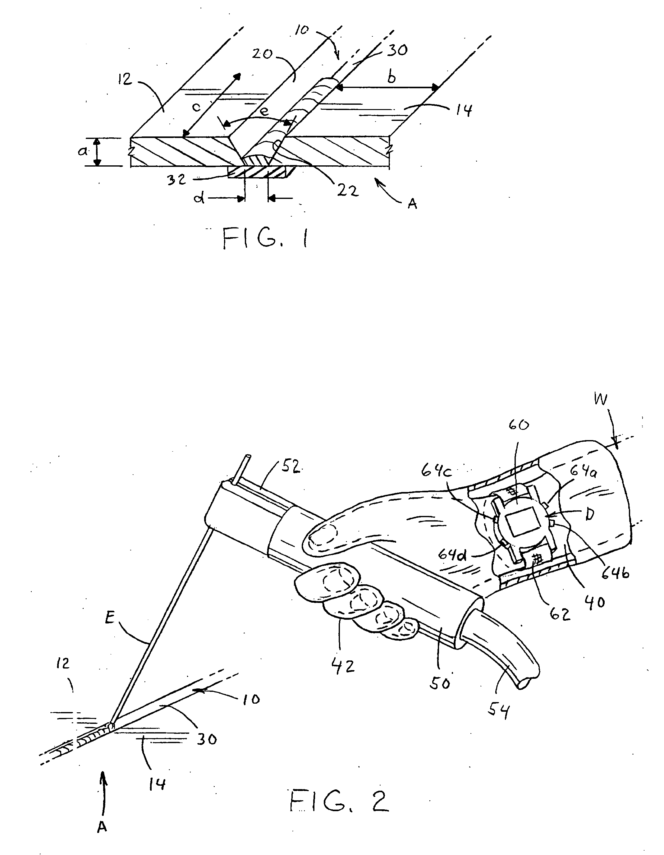
[0021] To determine the physical characteristics of a weld performed by a given welding wire, especially a stick electrode, many specifications require production of a standard test assembly, such as set forth in a specific welding procedure specification (WPS). The standardized test assembly for subsequent physical analysis of a weld by a specific electrode is illustrated in FIG. 1 where test assembly A involves a joint of metal deposited in groove 10 between spaced metal plates 12, 14. The spaced plates define test groove 10 and have a thickness a generally between ½ and ¾ inch with a width b greater than 5 inches. Length c of test groove 10 is greater than ten inches and is preferably twelve inches. Actually the total length of the test groove used in the production of assembly A is greater than test length C, shown later as length L. In the preferred embodiment, tapered walls 20, 22 have an included angle e of about 20 degrees and are spaced from each other a distance d defining...


PUM

PropertyMeasurementUnit
lengthaaaaaaaaaa
temperatureaaaaaaaaaa
widthaaaaaaaaaa

Abstract

A method of pacing a desired travel speed of a manual arc welding process performed by a welder for depositing weld metal on a workpiece and along a test groove with a given test length defined by a visible start location and a visual end location using a specified amount of energy distributed generally uniformly in the groove between the locations. The method comprises providing a power source with output leads and an arc current and an arc voltage; setting the output welding power of the power source; providing a consumable welding wire; connecting the output leads across the welding wire and the workpiece; determining the time T for the wire to traverse the test length to consume the specific amount of energy; marking the groove with a visible indicia spaced from the start location a given distance; associating a programmable haptic device with an exposed body part of the welder where the device has a tactile alarm activated after a programmed time t from start of the haptic device, which time t is coordinated with the given distance to give the desired travel speed; starting the haptic device when the operator commences welding at the start location and employs a manual rate of travel; and, changing the manual rate of travel according to the relationship of the wire to the indicia when the tactile alarm is activated.

Description

[0001] The present invention relates to the field of electric arc welding and more particularly to a method of pacing the travel speed of a welding operation used to form an assembly to test for physical properties. INCORPORATION BY REFERENCE [0002] The invention relates to the construction of a standard weld test assembly using a haptic device of the tactile alarm type. Such devices are well known and are shown in several patents, such as Shahoian 6,697,044 incorporated by reference herein. The haptic device actually employed in practicing the invention is a wrist mounted tactile alarm watch having settable alarm times for vibrating the base of the device worn on the wrist. Such device is sold for use in announcing the time to take a medication. An undated two page stacking sheet shows this medication device referred to as MeDose. This publication is incorporated by reference herein to show the type of haptic device using a tactile alarm for implementation of the present invention....

Claims


Application Information

Patent Timeline
Patent Type & Authority Applications(United States)
IPC IPC(8): B23K9/10
CPCB23K9/0008B23K9/0026
Inventor BILL, DONALD L.
Owner LINCOLN GLOBAL INC
Why Eureka
Try Eureka