Autonomous robot auto-docking and energy management systems and methods

a technology of autonomous robots and energy management systems, applied in the field of robots, can solve the problems of common, time-consuming, or dangerous, and wires buried below the surface on which the robot operates, and achieve the effects of reducing the application range, and reducing the risk of accidents

a technology of autonomous robots and energy management systems, applied in the field of robots, can solve the problems of common, time-consuming, or dangerous, and wires buried below the surface on which the robot operates, and achieve the effects of reducing the application range, and reducing the risk of accidents

US20070114975A1Active Publication Date: 2007-05-24IROBOT CORP

Image

  • Autonomous robot auto-docking and energy management systems and methods
  • Autonomous robot auto-docking and energy management systems and methods
  • Autonomous robot auto-docking and energy management systems and methods

Examples


Embodiment Construction

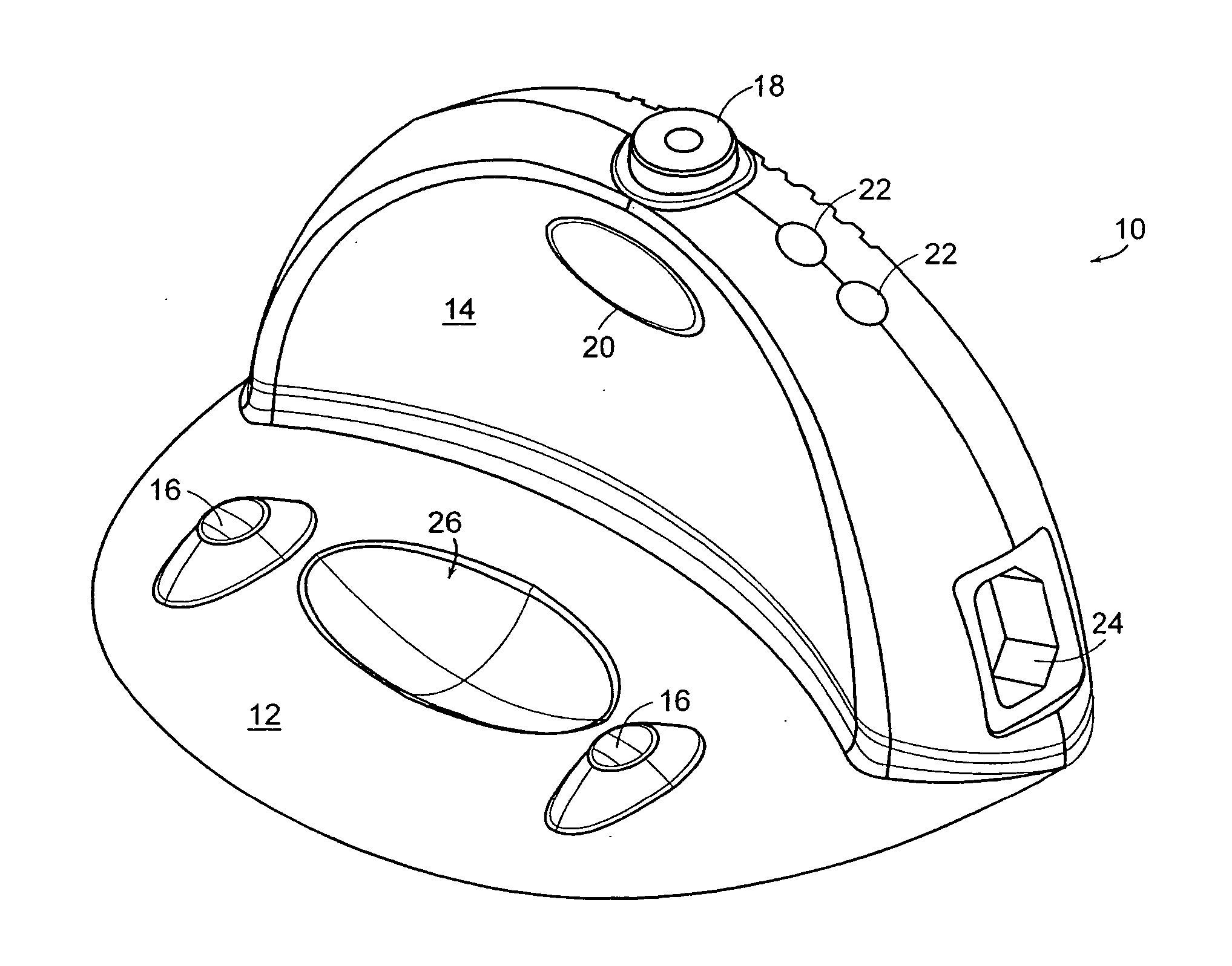
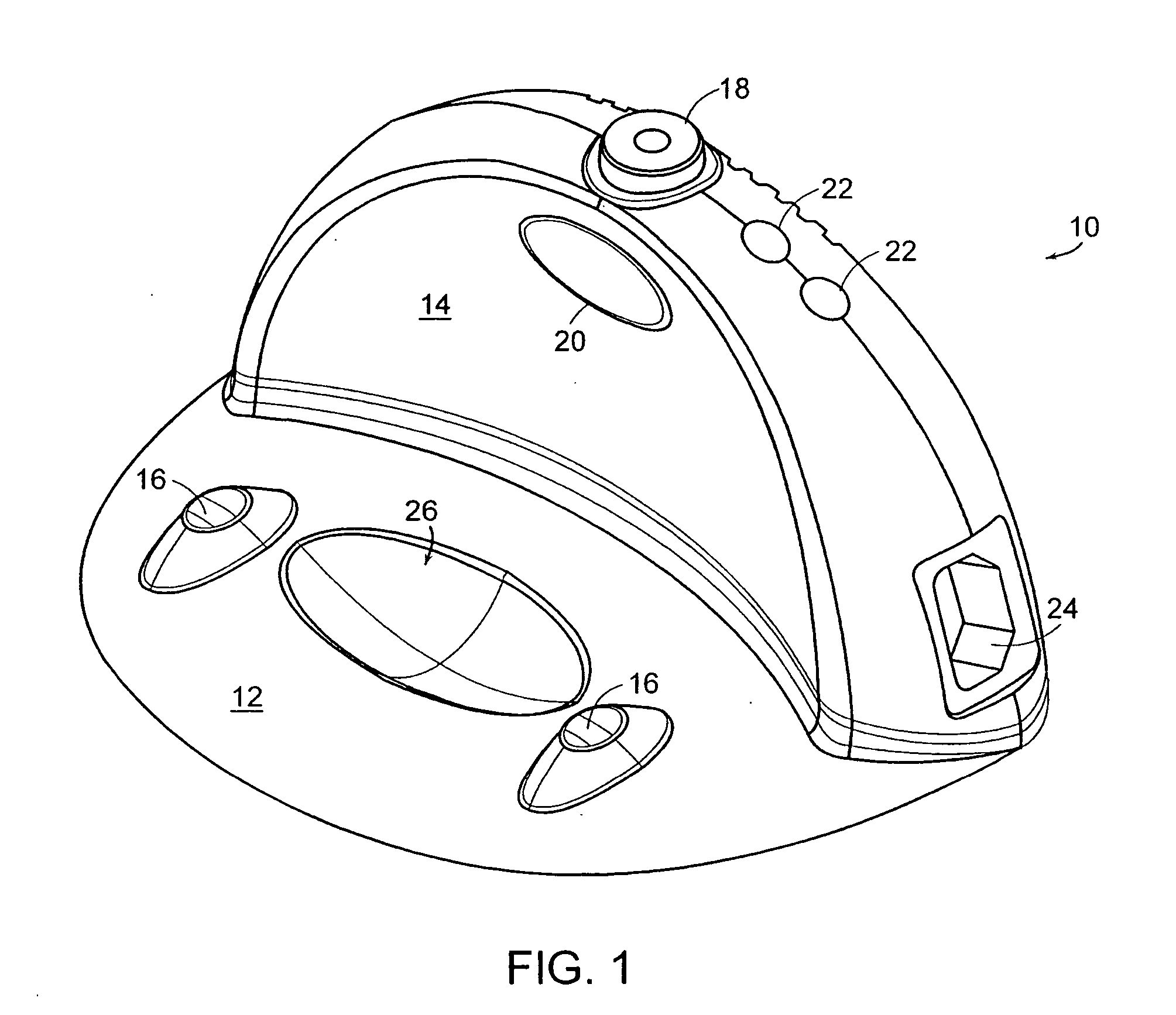
[0029]FIG. 1 is a schematic perspective view a base station 10 in accordance with one embodiment of the invention. The base station 10 includes both a substantially horizontal base plate 12 and a substantially vertical backstop 14. The base station 10 may be any of a variety of shapes or sizes, providing sufficient space for the desired components and systems, described below. The base plate 12 is generally parallel to the ground surface on which the base station 10 rests, but may have a slight upwards angle directed toward the backstop 14. By minimizing the angle of rise of the base plate 12, the robotic device (FIGS. 2A-2B) may easily dock with the station 10. Electrical charging contacts 16 are located on a top surface of the base plate 12, allowing them to contact corresponding contacts (FIG. 2B) on the underside of the robotic device. The contacts 16 or the,contacts on the robot may be either fixed or compliant. In the depicted embodiment, two contacts 16 (one positive, one neg...


PUM


Abstract

A method for energy management in a robotic device includes providing a base station for mating with the robotic device, determining a quantity of energy stored in an energy storage unit of the robotic device, and performing a predetermined task based at least in part on the quantity of energy stored. Also disclosed are systems for emitting avoidance signals to prevent inadvertent contact between the robot and the base station, and systems for emitting homing signals to allow the robotic device to accurately dock with the base station.

Description

TECHNICAL FIELD [0001] The present invention relates generally to robotic systems and, more specifically, to auto-docking and energy management systems for autonomous robots. BACKGROUND [0002] Automated robots and robotic devices are becoming more prevalent today and are used to perform tasks traditionally considered mundane, time-consuming, or dangerous. As the programming technology increases, so too does the demand for robotic devices that require a minimum of human interaction for tasks such as robot refueling, testing, and servicing. A goal is a robot that could be configured a single time, which would then operate autonomously, without any need for human assistance or intervention. [0003] Robotic devices and associated controls, navigational systems, and other related systems moving in this direction are being developed. For example, U.S. Pat. No. 6,594,844 discloses a Robot Obstacle Detection System, the disclosure of which is hereby incorporated by reference in its entirety....

Claims


Application Information

Patent Timeline
24 May 2007
Publication
US20070114975A1
IPC
H02J7/04
CPC
A47L9/2857; H02J7/0052; A47L9/2805; A47L9/2894; G01S1/16; G01S1/70; G05D1/0219; G05D1/0227
Inventors
COHEN, DAVID A.; OZICK, DANIEL