Front derailleur with mounting fixture

a technology of mounting fixture and derailleur, which is applied in the direction of mechanical equipment, transportation and packaging, etc., can solve the problems of variable adjustment of the orientation of the chain guide of the derailleur, and the inability to position the chain guide parallelly above the front sprock

Active Publication Date: 2007-05-24
SHIMANO INC
View PDF7 Cites 41 Cited by
  • Summary
  • Abstract
  • Description
  • Claims
  • Application Information

AI Technical Summary

Benefits of technology

[0012] One object of the present invention is to provide to make it possible to securely maintain the orientation of the front derailleur about the first adjustment axis in a mounting fixture for attaching the front derailleur to the frame.

Problems solved by technology

Since such mounting fixtures are fastened to the seat tube beforehand, the chain guide of the derailleur cannot be disposed in a parallel position directly above the front sprocket in the case of systems in which a band is formed as an integral part of the front derailleur, unless the orientation is adjusted about an axis parallel to the seat tube following mounting.
Consequently, a large force is caused to act on the contact bolt by the torque that is generated by the chain, so that there is a danger that the adjusted orientation will vary because of a slight looseness of the screw or the like.

Method used


Image

  • Front derailleur with mounting fixture
  • Front derailleur with mounting fixture
  • Front derailleur with mounting fixture

Examples


second embodiment

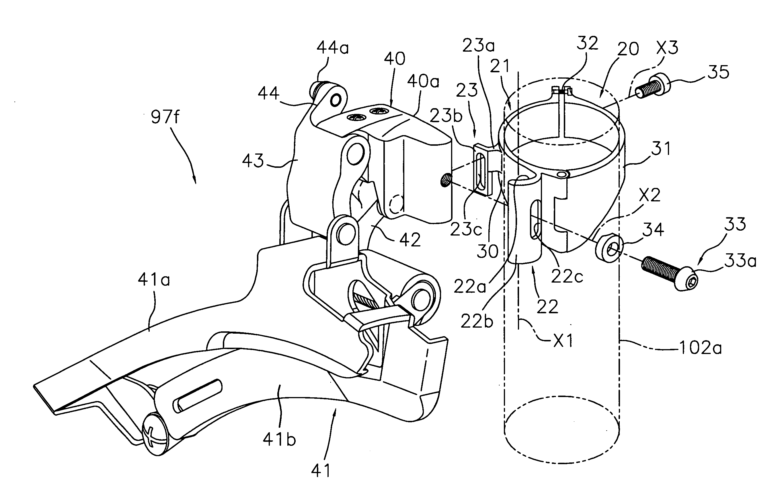
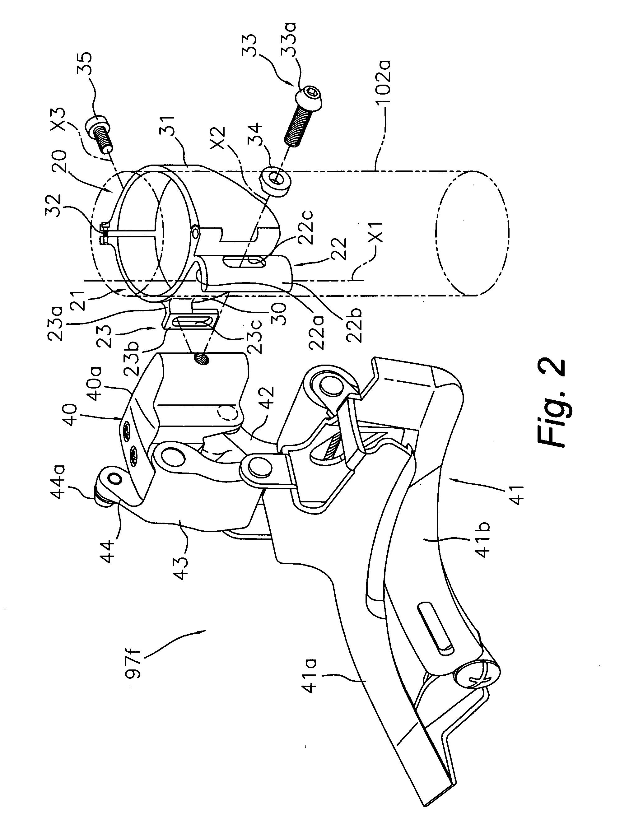
[0055] Referring now to FIG. 4, the front derailleur 97f is mounted to the seat tube 102a using a modified mounting fixture 120 in accordance with a second illustrated embodiment. In view of the similarity between the first and second illustrated embodiments, the parts of the second illustrated embodiment that are identical to the parts of the first illustrated embodiment will be given the same reference numerals as the parts of the first illustrated embodiment. Moreover, the descriptions of the parts of the second illustrated embodiment that are identical to the parts of the first illustrated embodiment may be omitted for the sake of brevity.

[0056] In the abovementioned embodiment, the connecting part 23b was installed on the front derailleur contact part 23 of the mounting fixture 20. However, as shown in FIG. 4, it would also be possible to provide a front derailleur contact part 123 of the mounting fixture 120 with an advancing and retracting part 123b that comes into contact w...

third embodiment

[0058] Referring now to FIG. 5, the front derailleur 97f is mounted to the seat tube 102a using a modified mounting fixture 220 in accordance with a third illustrated embodiment. In view of the similarity between the first and third illustrated embodiments, the parts of the third illustrated embodiment that are identical to the parts of the first illustrated embodiment will be given the same reference numerals as the parts of the first illustrated embodiment. Moreover, the descriptions of the parts of the third illustrated embodiment that are identical to the parts of the first illustrated embodiment may be omitted for the sake of brevity.

[0059] In the first and second embodiments, the front derailleur mounting part is fastened to the seat tube 102a by band clamping. However, as shown in FIG. 5, it is also possible to fasten the mounting fixture 220 to the seat tube 102a by fastening means such as welding or the like. This mounting fixture 220 has a bicycle frame fastening part 221...

fourth embodiment

[0061] Referring now to FIG. 6, a front derailleur 197f is mounted to the seat tube 102a using a modified mounting fixture 320 in accordance with a fourth illustrated embodiment. In view of the similarity between the first and fourth illustrated embodiments, the parts of the fourth illustrated embodiment that are identical to the parts of the first illustrated embodiment will be given the same reference numerals as the parts of the first illustrated embodiment. Moreover, the descriptions of the parts of the fourth illustrated embodiment that are identical to the parts of the first illustrated embodiment may be omitted for the sake of brevity.

[0062] In the abovementioned embodiment, a detachable fastening part or an advancing and retracting part was installed on the front derailleur contact part, but it is also possible to omit these and to merely establish contact the side surface 140a. In this case, if a gap is created between the front derailleur contact part and the side surface...


PUM


Abstract

A bicycle front derailleur is provided with a mounting fixture that is configured to maintain an angular orientation of the front derailleur about a mounting axis parallel to a center axis of a frame tube in a stable manner. The mounting fixture has a bicycle frame fastening part, a front derailleur mounting part and a front derailleur contact part. The bicycle frame fastening part is configured to be fastened to the seat tube. The front derailleur mounting part is disposed on the bicycle frame fastening part and configured to be fastened to the front derailleur so that fine adjustment is possible about the mounting axis disposed at a distance from the seat tube. The front derailleur contact part selectively contacts a side surface of the front derailleur on the side facing the seat tube in a position that is different from that of the front derailleur mounting part.

Description

CROSS-REFERENCE TO RELATED APPLICATIONS [0001] This application claims priority under 35 U.S.C. § 119 to Japanese Patent Application No. 2005-335811. The entire disclosure of Japanese Patent Application No. 2005-335811 is hereby incorporated herein by reference. BACKGROUND OF THE INVENTION [0002] 1. Field of the Invention [0003] This invention generally relates to a bicycle front derailleur that is fastened to the bicycle frame. More specifically, the present invention relates to a mounting fixture for mounting the bicycle front derailleur to a tubular member of the bicycle frame in a manner such that the angular position of the bicycle front derailleur can be finely adjusted relative to an axis that is parallel to a center axis of the tubular member of the bicycle frame. [0004] 2. Background Information [0005] Bicycling is becoming an increasingly more popular form of recreation as well as a means of transportation. Moreover, bicycling has become a very popular competitive sport fo...

Claims


Application Information

Patent Timeline
Patent Type & Authority Applications(United States)
IPC IPC(8): F16H61/00B62M9/135
CPCB62M9/135
Inventor ICHIDA, TADASHIFUJII, KAZUHIROODA, YOSHIHIRO
Owner SHIMANO INC
Why Eureka
Try Eureka