
Assembly consisting of a carrier part and a door interior part

Inactive Publication Date: 2007-05-31
INTEVA PROD FRANCE SAS
View PDF8 Cites 9 Cited by
  • Summary
  • Abstract
  • Description
  • Claims
  • Application Information

AI Technical Summary

Benefits of technology

[0007] Preferably, a protrusion is provided comprising a bent edge of the carrier part that surrounds the opening. The protrusion is formed in one piece with the carrier part and is a stamped portion thereof. The protrusion reliably resists shearing forces.
[0013] It is preferred that two recesses are provided in the door interior part, which surround the two studs. One recess is configured as a groove and the other recess takes up an oval region. The protrusions facing the carrier part engage in the recesses after positioning the carrier part on the door interior part. The recess configured as a groove has a diameter that corresponds to that of the protrusion, so that the protrusion circumferentially engages on a wall of the recess. The second recess, however, has a width corresponding to the diameter of the stud and a length that is larger than the diameter of the stud. It is only at a lateral wall of the second recess where the protrusion engages. This is why the stud can slightly “push away” the protrusion, so that manufacturing tolerances of the carrier part in the z-direction can be compensated for in the range of millimeters.

Problems solved by technology

Typically, the carrier parts have been fastened to the door interior part by expensive or multi-part screw connections.

Method used


Image

  • Assembly consisting of a carrier part and a door interior part
  • Assembly consisting of a carrier part and a door interior part
  • Assembly consisting of a carrier part and a door interior part

Examples


first embodiment

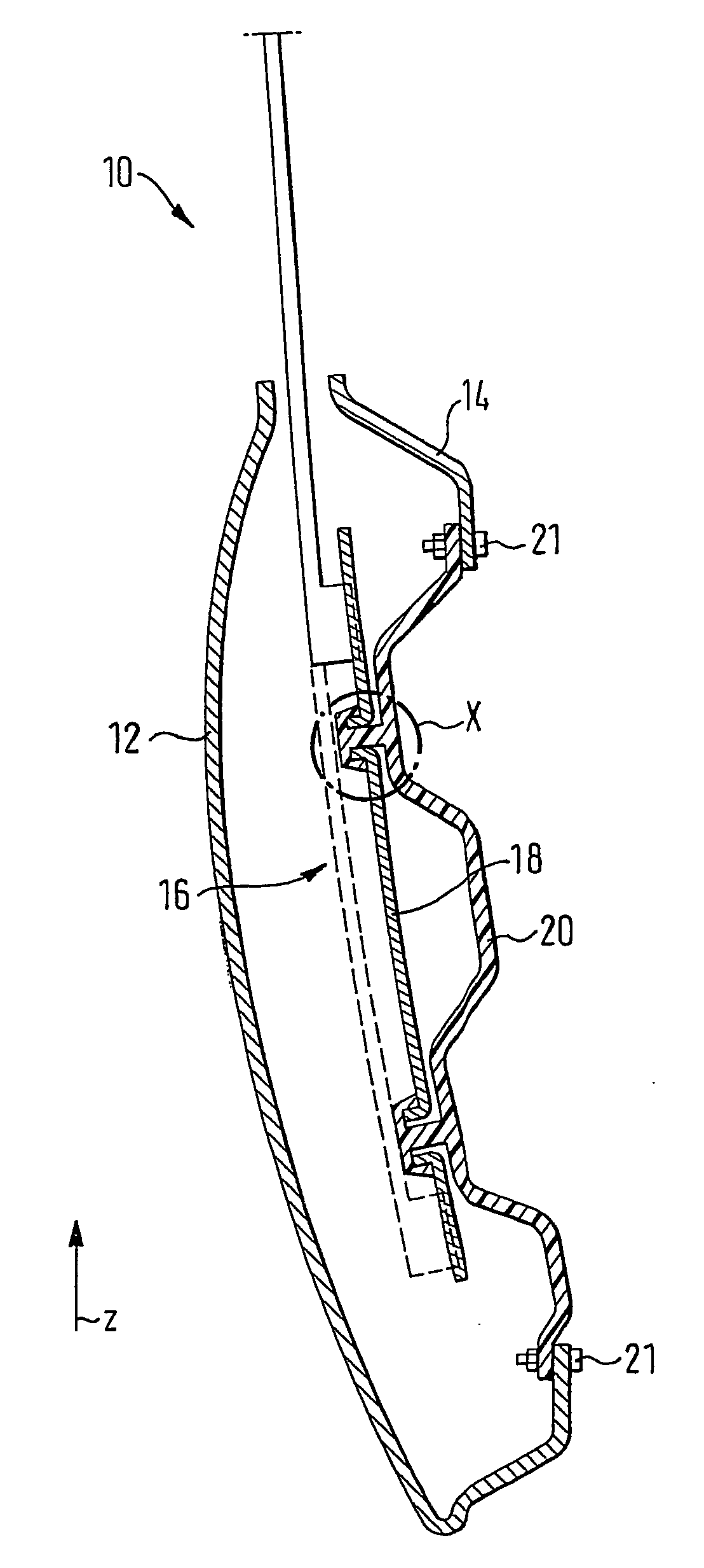
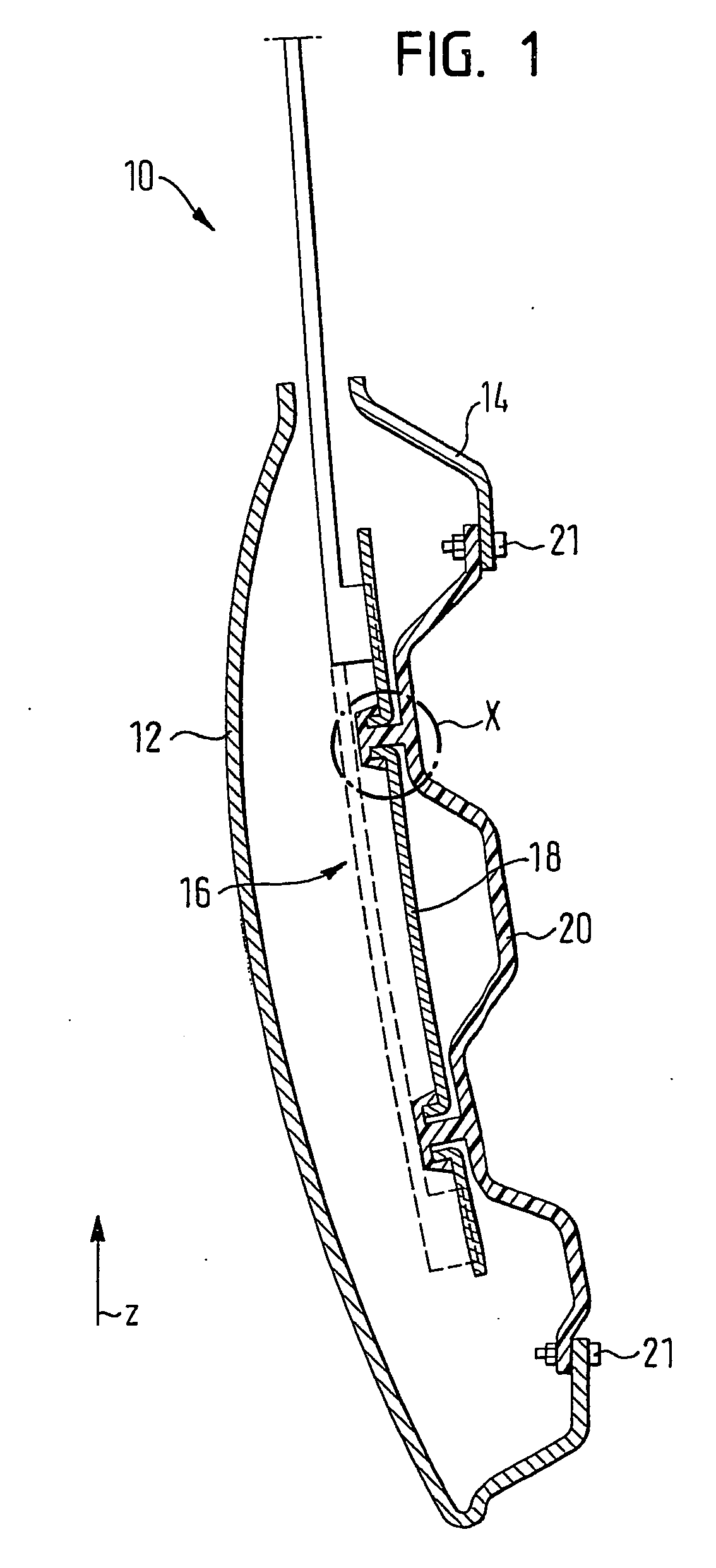
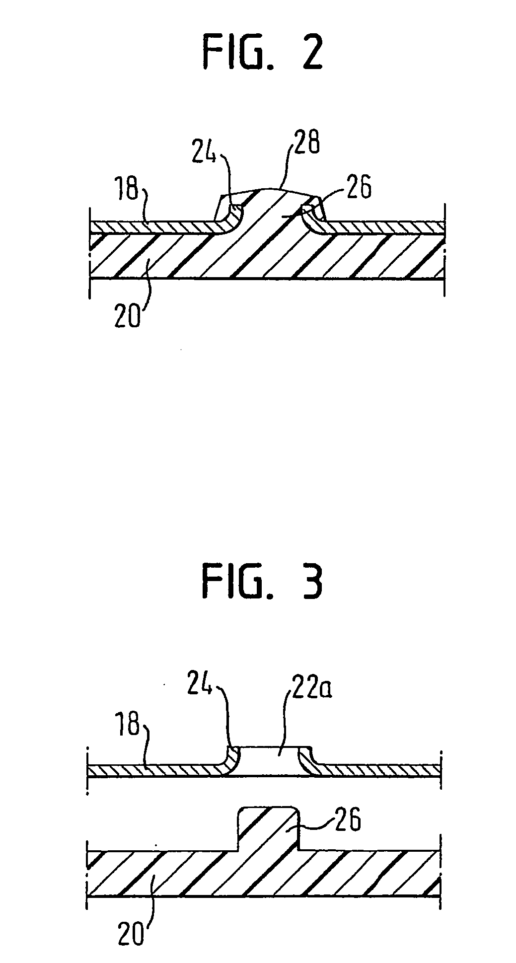
[0033] Positioning and attaching the rail 18 to the door interior part 20 is accomplished as follows: The rail 18 is oriented such that the two studs 26 of the door interior part 20 engage in the first and second openings 22a, 22b. The protrusions 24, after mounting the rail 18 to the door interior part 20, face away from the door interior part 20 (FIGS. 3 to 5). FIGS. 4 and 5 show the stud 26 that engages in the first opening 22a, which is the upper circular opening related to the illustration in FIG. 1. In this arrangement, an outer surface of the stud 26 circumferentially rests at the protrusion 24.

[0034] The lower stud 26 of the door interior part 20, related to the illustration in FIG. 1, engages in the second opening 22b and rests at the oval protrusion 24 only in sections, in particular at side edges (FIG. 5). This stud 26 therefore can assume various positions, and in this way compensates for manufacturing tolerances of the rail 18 in a z-direction.

[0035] When the rail 18 ...

second embodiment

[0036] FIGS. 6 to 9 show the assembly including the rail 18 and the door interior part 20.

[0037] The differences between the first and second embodiment will be explained in the following. The same reference symbols will be used for those components which are known from the first embodiment, and reference is made in this respect to the above explanations. Both the first and second openings 22a, 22b are circular in this embodiment.

[0038] Upper and lower recesses 30a, 30b surround the two cylindrical studs 26. The upper recess 30a, related to these Figures, is groove-shaped and has a diameter that corresponds to that of the stud 26. The lower recess 30b, which surrounds the lower stud 26, related to these Figures, takes up an oval area.

[0039] A depth of the upper and lower recesses 30a, 30b corresponds to a height of the protrusions 24, or is selected so as to be somewhat deeper, so that the protrusions 24 can engage in the upper and lower recesses 30a, 30b with their entire height,...


PUM


Abstract

An assembly includes a carrier part and a door interior part. The carrier part has at least one opening and the door interior part has a one-piece stud capable of engaging in the opening. The one-piece stud has a plastically deformed portion that fastens the carrier part to the door interior part.

Description

RELATED APPLICATIONS [0001] The application claims priority to German Application No. 20 2005 018 470.5 which was filed on Nov. 25, 2005. BACKGROUND OF THE INVENTION [0002] The invention relates to an assembly that includes a carrier part and a door interior part, in particular for a motor vehicle, with the carrier part having at least one opening and the door interior part having a one-piece stud capable of engaging in the opening. [0003] The carrier part is engaged by a carriage of a window lifter system, for instance. For the purpose of a simple installation, components of the window lifter system are pre-assembled on the carrier part and conveyed to a car body as a pre-assembled unit. The pre-assembled unit can then be mounted to the door interior part. The term “door interior part” is to be understood to refer to inner structural parts of lateral portions of the car body, in particular of a vehicle door. [0004] Typically, the carrier parts have been fastened to the door interio...

Claims


Application Information

Patent Timeline
IPC IPC(8): B60J5/04
CPCB60J5/0416E05F11/382E05Y2201/684E05Y2600/10E05Y2600/508E05Y2900/55
Inventor SEIBERT, JENS
Owner INTEVA PROD FRANCE SAS
Learn More