LCD module and control method

a technology of lcd module and control method, applied in the direction of instruments, static indicating devices, etc., can solve the problems of non-uniform luminance of varying severity, and achieve the effect of improving flickering and non-uniform luminance problems

Inactive Publication Date: 2007-05-31
HUNG JIMI
View PDF1 Cites 4 Cited by
  • Summary
  • Abstract
  • Description
  • Claims
  • Application Information

AI Technical Summary

Benefits of technology

[0026] Based on the TFT liquid crystal display module and reversal signal control method according to the present invention, the reversal signal provided by the ...

Problems solved by technology

In light that when data displayed on a LCD panel and the reversal state generated by a reversal signal on the panel are synchronous, the problems of flickering and non-uniform l...

Method used


Image

  • LCD module and control method
  • LCD module and control method
  • LCD module and control method

Examples


Embodiment Construction

[0035] Preferred embodiments of the invention accompanied by drawings will be fully described. But it should be noted that people familiar with the skill can modify the invention described herein to obtain the same effect. Thus the description below is a general disclosure which does not mean limiting the invention.

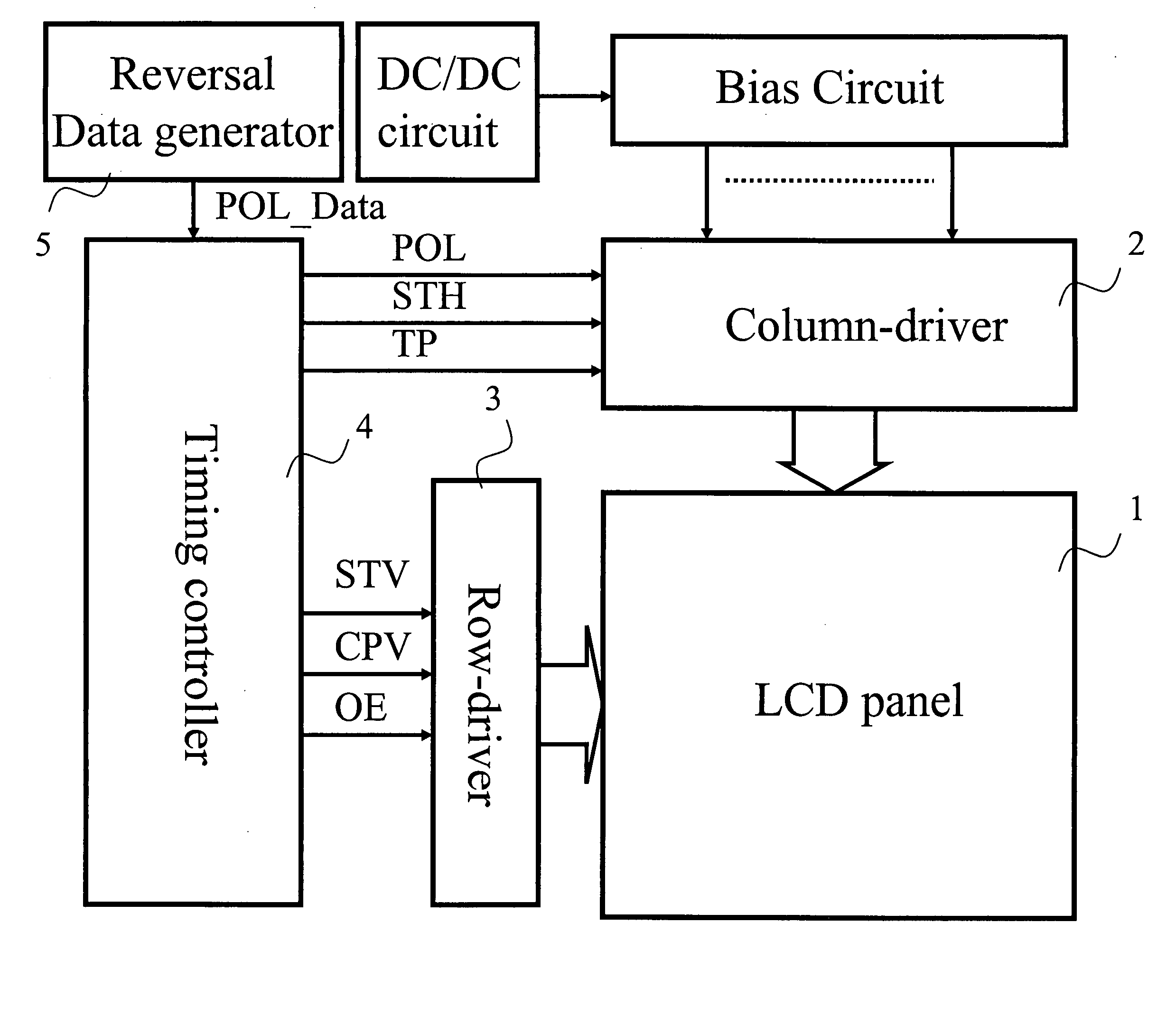
[0036] Referring to FIG. 4, a block diagram of the driver circuit of a TFT liquid crystal display module according to the invention is shown. The TFT liquid crystal display module comprises a LCD panel 1, a column-driver 2, a row-driver 3 and a timing controller 4, wherein the timing controller 4 provides a column start signal STH, a reversal signal POL, and a latch signal TP to the column-driver 2, and a row start signal STV, a row clock signal CPV, and an output enable signal OE to the row-driver 3.

[0037] In a preferred embodiment of the invention, the TFT liquid crystal display module includes a reversal data generator 5. The reversal data generator 5 outputs a rever...


PUM


Abstract

A TFT liquid crystal display (LCD) module comprising a timing controller and a reversal data generator is disclosed. The timing controller provides a plurality of signals to the column-driver and row-driver of LCD panel. The reversal data generator outputs a reversal data signal to the timing controller, which in turn outputs a non-periodic reversal signal to the column-driver. The generation of reversal data signal by the reversal data generator is independent of the timing of the timing controller, or the reversal data signal is a non-periodic signal and the non-periodic reversal signal will change its state within a specific time range posterior to the column start signal.

Description

BACKGROUND OF THE INVENTION [0001] 1. Field of the Invention [0002] The present invention relates to a signal control circuit and control method, more particularly, to a TFT LCD module and control method that alters the characteristics of the reversal signal. [0003] 2. Description of the Related Art [0004]FIG. 1 is the driver circuit diagram of a conventional TFT liquid crystal display module. The TFT liquid crystal display module comprises a liquid crystal display panel (LCD panel) 1, a column-driver 2, a row-driver 3 and a timing controller 4, wherein data displayed by LCD panel 1 are controlled by the timing controller 4, which sends respectively column start signal (STH), reversal signal (POL), latch signal (TP), row start signal (STV), row clock signal (CPV), and output enable signal (OE) to the LCD panel 1 through the row-driver 3 and the column-driver 2. [0005] Among the LCD modules on the market, timing control signals are more complicated as the specifications for panel res...

Claims


Application Information

Patent Timeline
IPC IPC(8): G09G3/36
CPCG09G3/3614G09G2320/0233G09G2320/0247
Inventor SU, PO-HSIEN
Owner HUNG JIMI
Why Eureka
Try Eureka