
Driving circuit and lighting apparatus for light emitting diode

a technology of driving circuit and lighting apparatus, which is applied in the direction of lighting apparatus, electrical equipment, light sources, etc., can solve the problems of increasing manufacturing costs flickering at timing, and circuit of light emitting apparatus becoming more complicated, so as to improve flicker, light efficiency, and dimming characteristics

Active Publication Date: 2017-02-23
SEOUL SEMICONDUCTOR
View PDF5 Cites 14 Cited by
  • Summary
  • Abstract
  • Description
  • Claims
  • Application Information

AI Technical Summary

Benefits of technology

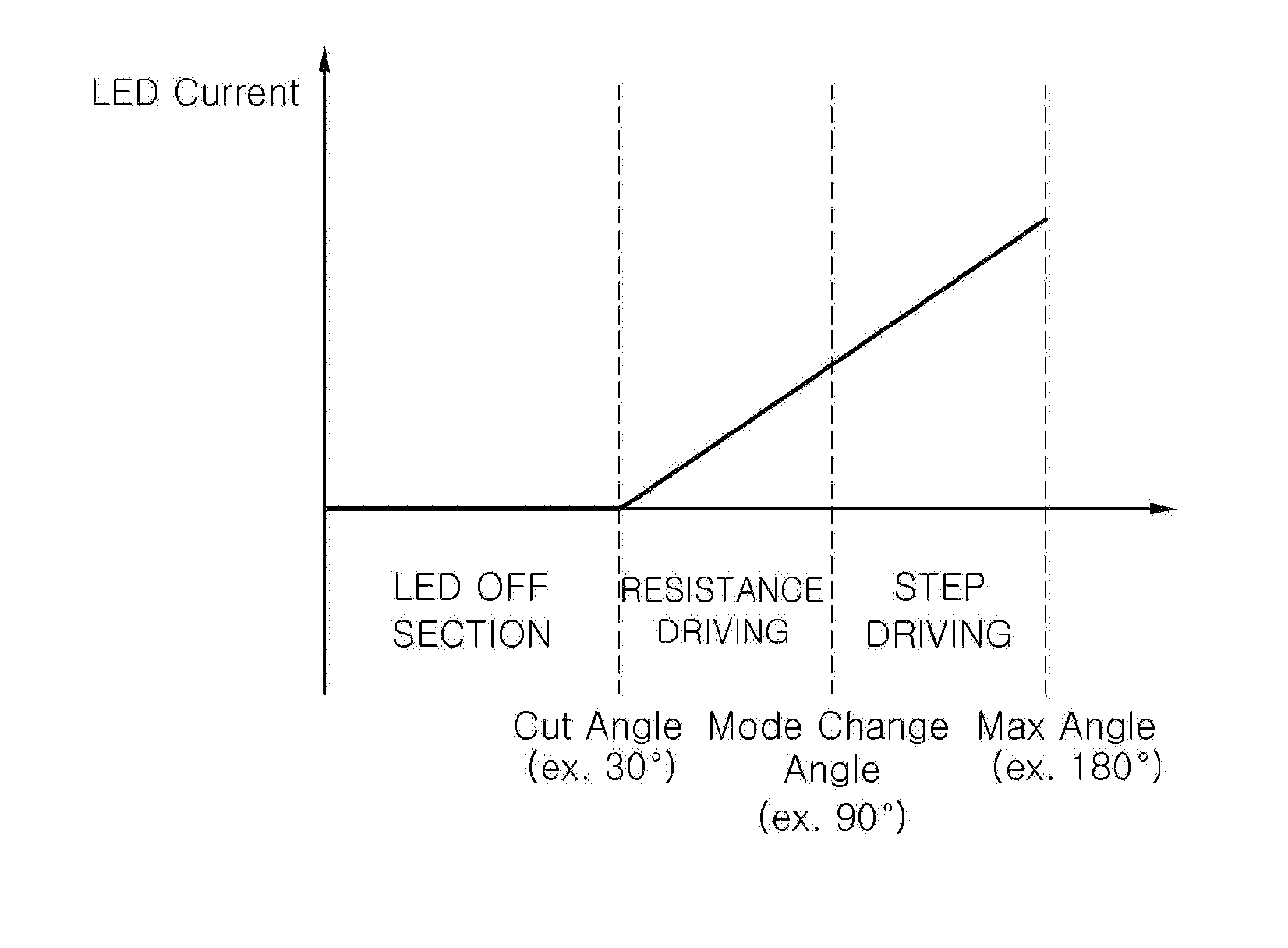
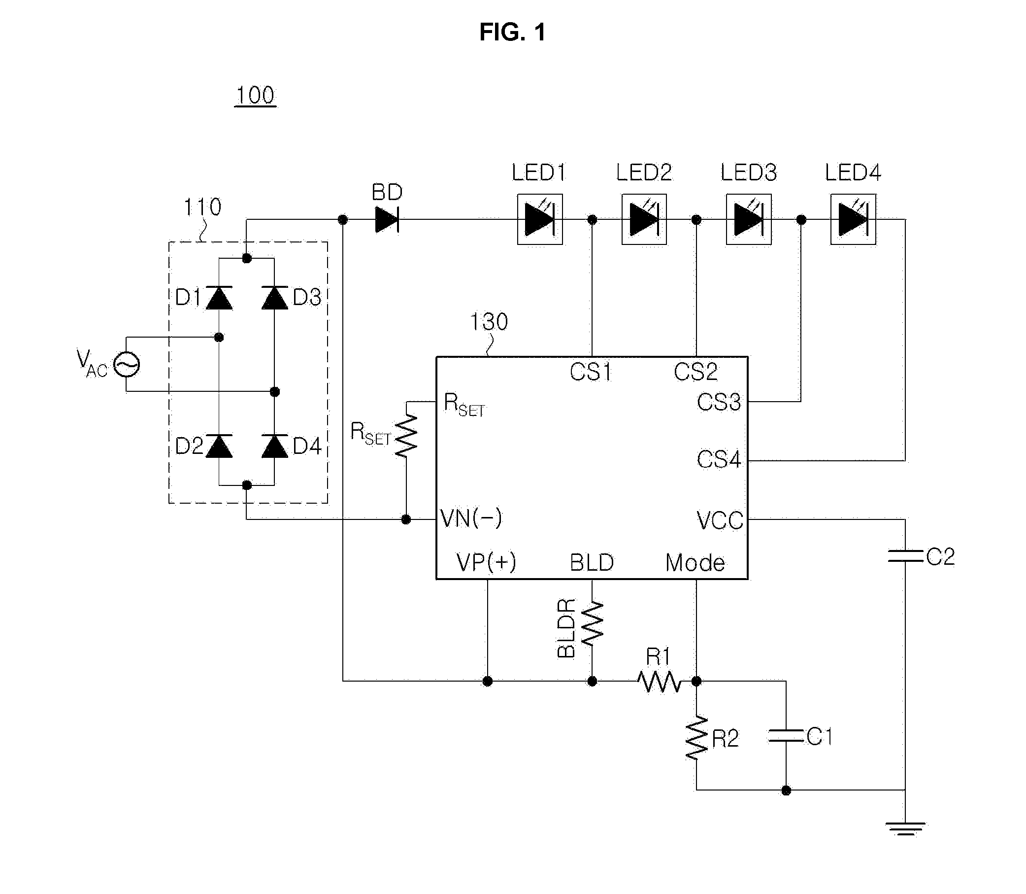
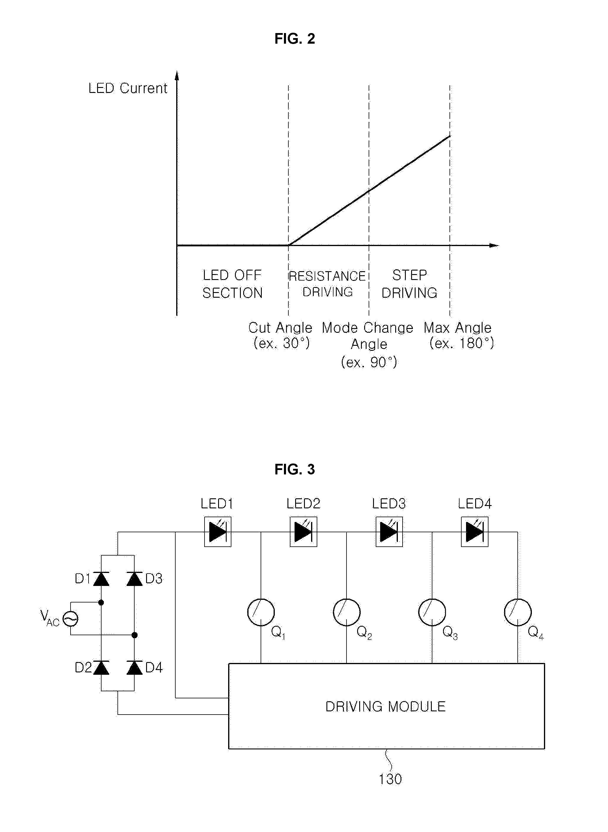
The present invention provides a driving circuit and lighting apparatus for a light emitting diode that can improve flickering, light efficiency, and dimming characteristics. This is achieved by a driving module that detects the dimming level of the input AC voltage and selects one of three driving modes of a stop mode, a resistance driving mode, or a sequential driving mode depending on the detected dimming level. The choice of driving modes improves the flickering and light efficiency of the light emitting diode. The disclosed driving circuit includes a dimmer, rectifier, and driving module, while the lighting apparatus includes a dimmer, rectifier, driving module, and multiple light emitting diode groups that emit light based on the control of the driving module.

Problems solved by technology

Therefore, there is a problem in that a circuit of the light emitting apparatus is becoming more complicated and manufacturing costs thereof are rising.
However, the driving circuit for a light emitting diode based on the general sequential driving scheme may brings about the flicker at timing when each of the light emitting diode groups is sequentially driven.
In particular, the driving circuit for the light emitting diode based on the general sequential driving scheme may bring about a flicker in a section where it is progressed from a high forward voltage level to a low forward voltage level.

Method used


Image

  • Driving circuit and lighting apparatus for light emitting diode
  • Driving circuit and lighting apparatus for light emitting diode
  • Driving circuit and lighting apparatus for light emitting diode

Examples


Embodiment Construction

[0046]Exemplary embodiments of the present invention will be described in detail with reference to the accompanying drawings. These exemplary embodiments will be described in detail for those skilled in the art in order to practice the present invention. It should be appreciated that various exemplary embodiments of the present invention are different from each other, but do not have to be exclusive. For example, specific shapes, structures, and characteristics described in the present specification may be implemented in another exemplary embodiment without departing from the spirit and the scope of the present invention in connection with an exemplary embodiment. In addition, it should be understood that a position or an arrangement of individual components in each disclosed exemplary embodiment may be changed without departing from the spirit and the scope of the present invention. Therefore, a detailed description to be described below should not be construed as being restrictive...


PUM


Abstract

Disclosed herein are a driving circuit and a lighting apparatus for a light emitting diode capable of improving a flicker, light efficiency, and electrical characteristics. The disclosed driving circuit for a light emitting diode includes: a dimmer modulating an AC voltage input depending on a selected dimming level; a rectifier full-wave rectifying the modulated AC voltage output from the dimmer to generate and output a driving voltage; and a driving module receiving the driving voltage of the rectifier to detect the selected dimming level and controlling a driving mode of a plurality of light emitting diode groups depending on the detected dimming level, in which the driving module selects one of a resistance driving mode driving all the plurality of light emitting diode groups and a sequential driving mode sequentially driving the plurality of light emitting diode groups to improve light efficiency and electrical characteristics.

Description

CROSS-REFERENCE TO RELATED APPLICATIONS[0001]This application claims priority from and the benefit of Korean Patent Application No. 10-2015-0118034, filed on Aug. 21, 2015, and Korean Patent Application No. 10-2015-0189712, filed on Dec. 30, 2015, which are hereby incorporated by reference for all purposes as if fully set forth herein.BACKGROUNDField[0002]The present invention relates to a driving circuit and a lighting apparatus for a light emitting diode, and more particularly, to a driving circuit and a lighting apparatus for a light emitting diode capable of improving a flicker, light efficiency, and electrical characteristics.Discussion of the Background[0003]Generally, a diode device for light emission such as a light emitting diode (LED) may be driven only by direct current (DC) power due to diode characteristics. Therefore, a light emitting apparatus using the existing light emitting diode has been restrictively used and should include separate circuits such as a switching m...

Claims


Application Information

Patent Timeline
IPC IPC(8): H05B33/08H05B37/02H05B44/00
CPCH05B33/0845H05B33/0809H05B33/083H05B37/0281H05B37/0227H05B45/00H05B45/37H05B45/48H05B45/10H05B45/3575H05B45/345H05B45/31H05B45/325H05B47/14H05B45/36Y02B20/40H05B47/16
Inventor LIM, KWANG BEAJIN, SUNG HOHAN, SANG WOOKJONG, YOUNG DO
Owner SEOUL SEMICONDUCTOR
Learn More