Toner container and image forming apparatus

a technology which is applied in the field of toner containers and image forming apparatus, can solve the problems of disadvantages of toner containers in patent documents 1 to 3 or so in terms of operability/workability upon their attachment/detachment, and the user is difficult to check that the operation is performed properly, and the plurality of operations are implemented for the attachment/detachment operation

Active Publication Date: 2007-05-31
RICOH KK
View PDF75 Cites 173 Cited by
  • Summary
  • Abstract
  • Description
  • Claims
  • Application Information

AI Technical Summary

Benefits of technology

[0026] It is an object of the present invention to at least

Problems solved by technology

However, the toner containers in Patent documents 1 to 3 or so are disadvantages in terms of operability/workability upon its attachment/detachment (replacement).
A first disadvantage is such that the attachment/detachment operation to/from the toner-container holder is implemented with a plurality of operations.
A second disadvantage is such that it is difficult for the user to check that the operation is performed properly nearly until the completion of the attachment operation.
More specifically, the user cannot feel certain that the operation is correct at the point in time when the operation of opening the main-body cover and the operation of placing the toner container on the toner-container holder are complete.
A third disadvantage is such that the upper side of the toner-container holder is restricted in terms of layout.
However, the toner storage container accordi

Method used


Image

  • Toner container and image forming apparatus
  • Toner container and image forming apparatus
  • Toner container and image forming apparatus

Examples


first embodiment

[0115] A first embodiment of the present invention is explained in detail below with reference to FIG. 1 to FIG. 16.

[0116] The configuration and operation of the overall image forming apparatus are explained first with reference to FIG. 1 to FIG. 4.

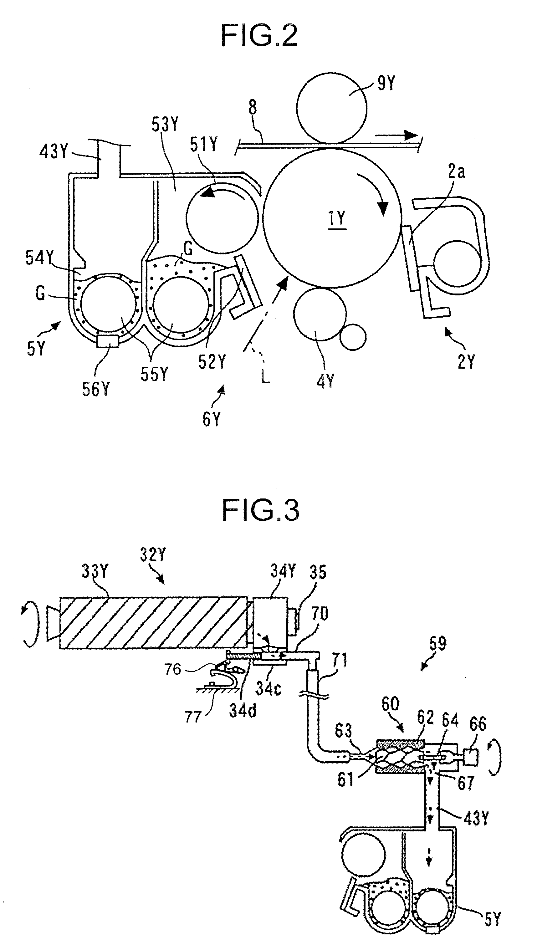
[0117]FIG. 1 is an overall schematic of a printer as the image forming apparatus, FIG. 2 is an enlarged view of an imaging unit of the image forming apparatus, FIG. 3 is a schematic of a toner supply path thereof, and FIG. 4 is a perspective view of a part of a toner-container holder.

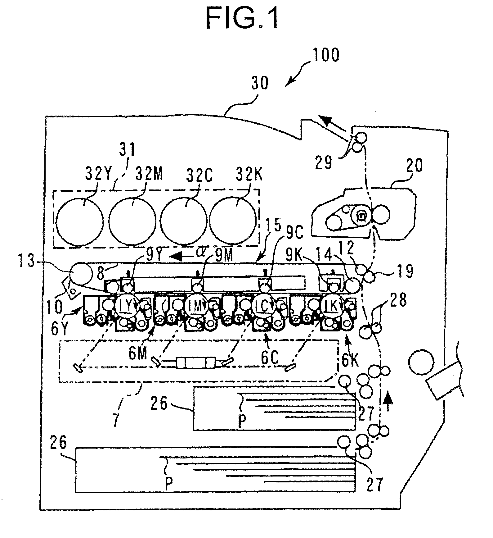
[0118] As shown in FIG. 1, four toner containers 32Y, 32M, 32C, and 32K correspond to colors (yellow, magenta, cyan, and black) and are detachably (replaceably) arranged in a toner-container holder 31 which is provided in the upper side of the main body of the image forming apparatus 100.

[0119] Provided in the lower side of the toner-container holder 31 is an intermediate transfer unit 15. Imaging units 6Y, 6M, 6C, and 6K corresponding to the colors (yell...

second embodiment

[0237] A second embodiment of the present invention is explained in detail below with reference to FIG. 17 to FIG. 19.

[0238]FIG. 17 is a cross-section of the head side of a toner container according to the second embodiment, which corresponds to that of FIG. 6 according to the first embodiment.

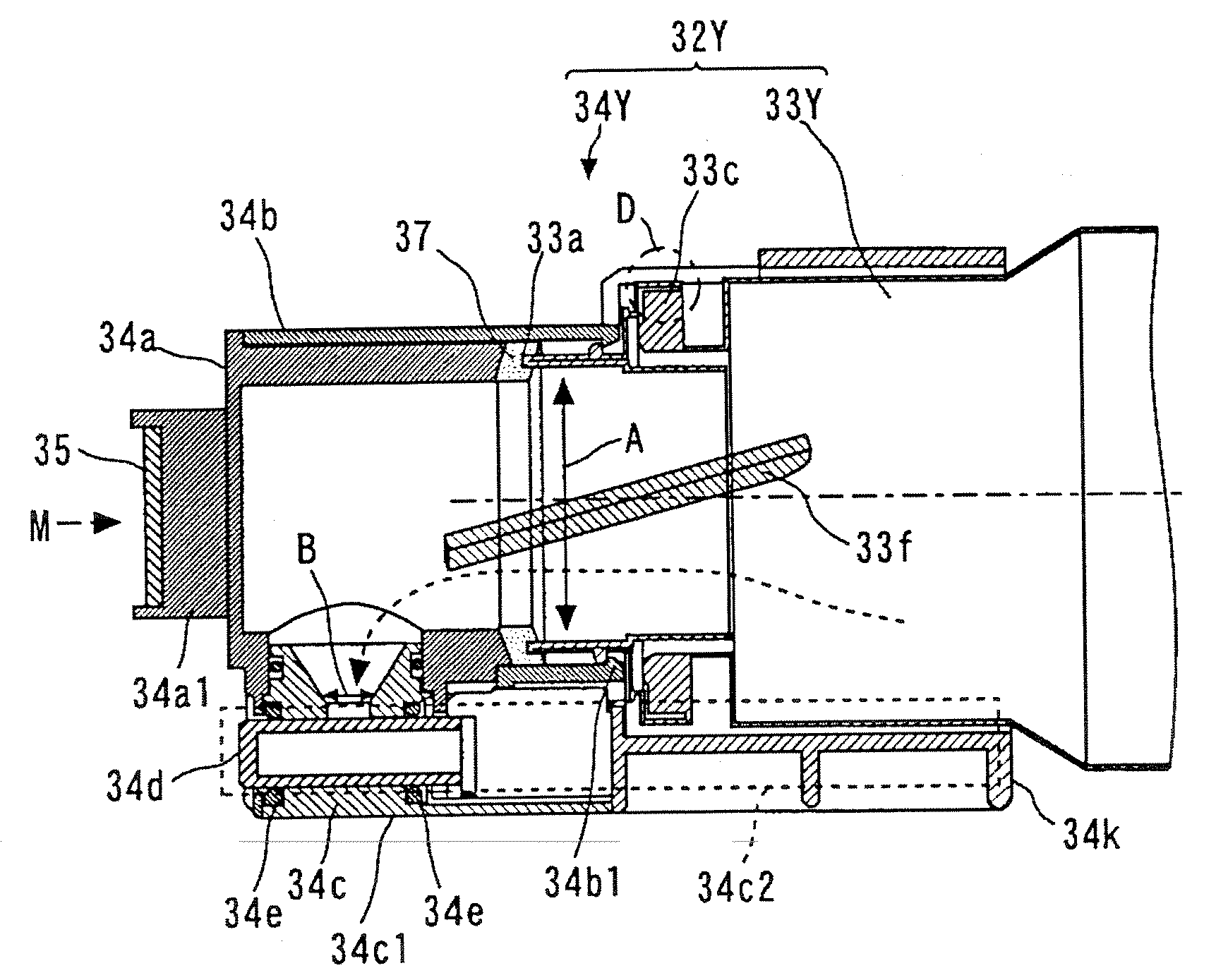
[0239] Referring to FIG. 17, the toner container 32Y according to the second embodiment is different from that of the first embodiment in a point that a compression spring 34f is provided as a member for applying biasing force to the held portion 34Y. More specifically, the compression spring 34f for biasing the plug member 34d in the direction of closing the toner outlet B is provided on the right-hand side of the plug member 34d.

[0240] The attachment / detachment operation of the toner container 32Y to / from the toner-container holder 31 is explained below with reference to FIG. 18 and FIG. 19.

[0241]FIG. 18A is a schematic of how the toner container 32Y for yellow is attached to the toner-c...

third embodiment

[0259] A third embodiment of the present invention is explained in detail below with reference to FIG. 20.

[0260]FIG. 20 is a perspective view of a toner container according to the third embodiment, which corresponds to FIG. 5 according to the first embodiment. In the third embodiment, the shape of the sliding portion 34c1 formed in the held portion 34Y is different from that of the embodiments.

[0261] As shown in FIG. 20, in the toner container 32Y according to the third embodiment, the first sliding portion 34c1 of the held portion 34Y is two convex portions (rib) that protrude toward the sliding face 31a of the toner-container holder 31, different from the sliding portion which is formed with the flat portion in the embodiments. More specifically, two convex portions 34c1 as the sliding portion 34c1 are formed so as to have height contactable with the sliding face 31a (they are formed so that the height in the vertical direction is equivalent to the sliding face 31a), and are ext...


PUM


Abstract

A toner container detachably attached to a toner-container holder of a main body of an image forming apparatus includes a container body that includes an opening, and discharges toner contained in the container body, from the opening; and a held portion that is held by the toner-container holder in a non-rotating manner. The held portion includes an open/close member for opening/closing the toner outlet in synchronization with an attachment/detachment operation of the held portion to/from the toner-container holder.

Description

CROSS-REFERENCE TO RELATED APPLICATIONS [0001] This application claims the benefit of U.S. Provisional Application Ser. No. 60 / 850,675, filed Oct. 11, 2006 and entitled “Toner Container and Image Forming Device” which is incorporated herein by reference. [0002] The inventions in this application are related to the inventions disclosed in the following Japanese patent applications: 2005-167298 filed Jun. 7, 2005, 2005-198355 filed Jul. 7, 2005, 2005-203370 filed Jul. 12, 2005, 2005-223438 filed Aug. 1, 2005, 2005-304216 filed Oct. 19, 2005, 2005-313616 filed Oct. 28, 2005, 2006-013293 filed Jan. 23, 2006, and 2006-029246 filed Feb. 7, 2006, and PCT patent application PCT / JP2006 / 311391 filed Jun. 7, 2006, each of which is incorporated herein by reference and may be utilized with any embodiment or feature disclosed herein.BACKGROUND OF THE INVENTION [0003] 1. Field of the Invention [0004] The present invention generally relates to a toner container detachably attached to the main body ...

Claims


Application Information

Patent Timeline
IPC IPC(8): G03G15/08
CPCG03G2215/0668G03G2215/067Y10S222/01G03G15/0855G03G15/0877G03G15/0886G03G15/0865G03G15/0872
Inventor TAGUCHI, NOBUYUKIKATSUYAMA, GOROKURENUMA, TAKEROHYOSHIZAWA, HIDEOYAMANE, MASAYUKI
Owner RICOH KK
Why Eureka
Try Eureka